I am blind or visually impaired: the story in one minute
Third Eye Kit

THE ENGINEERING RECORD, FILE 05 OF 19

The Reflex controller

READboth grids on the sensor I2C bus, the radar on UART, the IMUFUSEa per column nearest distance mapthe handoffs of docs/04DETECTdrop offs from the ground gridmovers from the radarTHREE LAWStwenty amplitude and rhythm commandsWRITEthe twenty commands through the actuator I2C busWATCHDOGserviced every tickbrownout or a missed tick resets to all motors offevery tick, then again. The RP2350's hardware float runs the fusion; signed boot protects the firmware; brownout and watchdog reset to a safe state.
One loop, two buses, nothing upstream can block it. The Reflex reads, fuses, applies the three laws, writes the motors, and services the watchdog every tick. Two I2C buses keep a stuck actuator write from ever delaying a sensor read. The Reflex has no data dependency on the Spine or the phone; it only transmits. Source: docs/05.
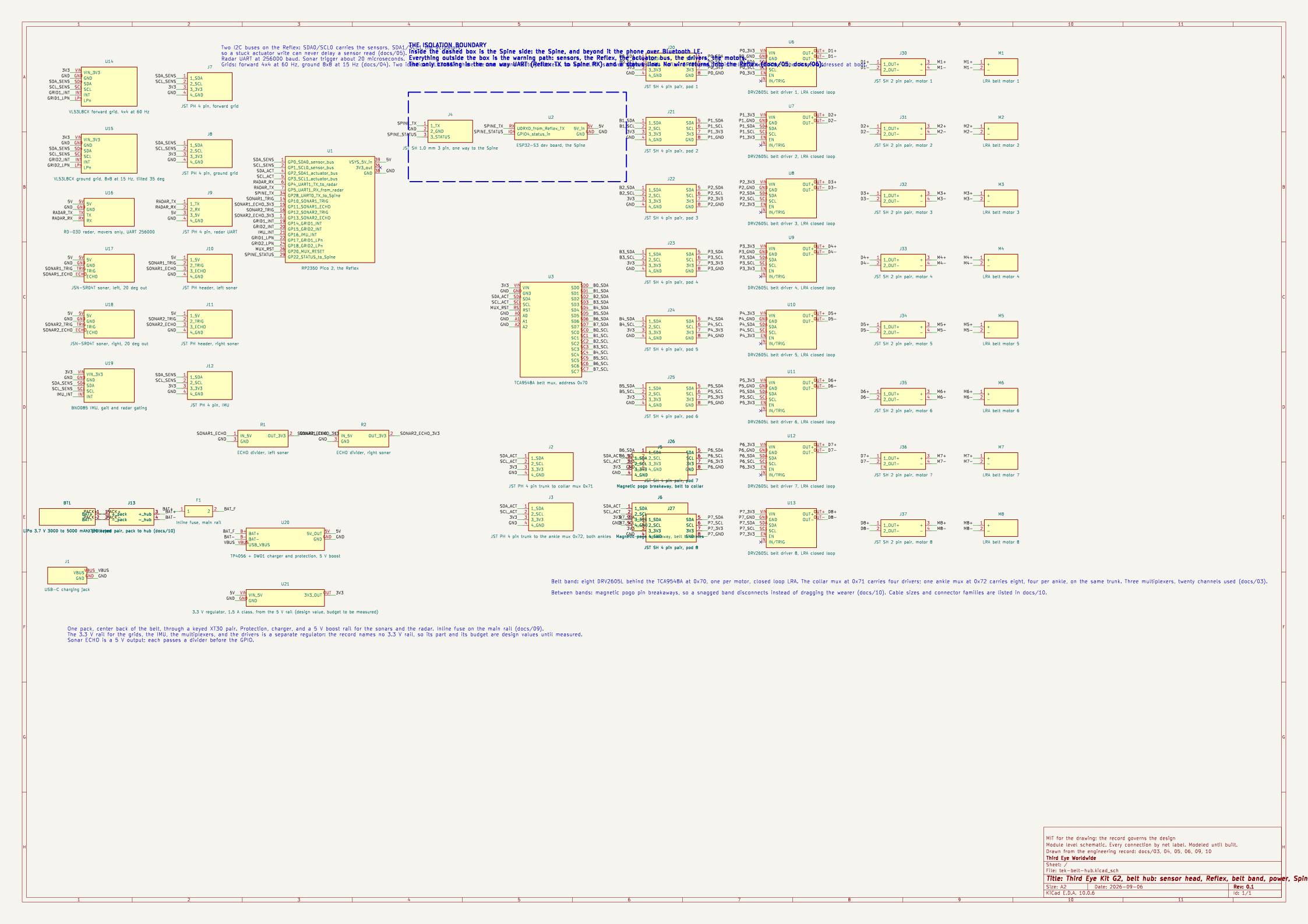
The belt hub schematic sheet: sensor modules on the left, the RP2350 Pico 2 in the center with its labeled pins, a dashed isolation boundary with the ESP32-S3 Spine to its right, the belt multiplexer and eight driver and motor pairs on the right, and the battery, fuse, charger and USB-C jack at the bottom left.
The belt hub schematic. Rendered by kicad-cli from the KiCad file in the repository: the two laser grids and the IMU on the Reflex's sensor I2C bus, the radar on its UART, the two sonars on trigger and echo lines; the belt multiplexer at 0x70 with its eight DRV2605L drivers and coin LRAs on the actuator bus; the trunk connectors and magnetic breakaways to the collar and ankle multiplexers; the pack, the fuse, the charger and the 5 V boost; and the one way link to the Spine across the isolation boundary. Every connection is a named net. kicad-cli's electrical rules check returns zero violations at its default severities. A module level schematic, modeled until built. Source: hardware/kicad/tek-belt-hub.kicad_sch, drawn from docs/03, 04, 05, 06, 09, 10.

Same price, near identical footprint, and it adds what the safety loop needs.

RP2350: dual Arm Cortex-M33 at 150 MHz with hardware single precision floating point and DSP instructions, 520 kB SRAM in 10 banks, Arm TrustZone, signed boot, 8 kB OTP for keys, SHA-256, hardware TRNG, glitch detectors, 2 I2C, 2 SPI, 2 UART, 12 PIO state machines, hardware watchdog.

Why it matters: the per column fusion and drop off detection run in hardware float instead of software float; the buffers for two grids plus radar tracks fit in SRAM; signed boot protects the safety firmware from a bad flash.

Alternatives: RP2040 (works today, no FPU); STM32G4 (excellent hard real time, single core, keep as fallback if RP2350 supply fails); ESP32 alone (rejected, its radio stack makes hard real time unclean; it stays as the Spine only).

The loop: read both grids on the sensor I2C bus and the radar on UART, fuse to a per column nearest distance map, detect drop offs, apply the three laws to produce 20 amplitude and rhythm commands, write them through the actuator I2C bus, service the watchdog every tick. Two I2C buses so a stuck actuator write can never delay a sensor read. Brownout and watchdog reset to a safe state with all motors off.

Isolation: the Reflex has no data dependency on the Spine or the phone. It only transmits. Nothing upstream can block it.

Source: docs/05-reflex-controller.md, the engineering record. Every number on this page is read from that file. If a fact is not in the record, it is measured on the bench, or it stays off this site.