I am blind or visually impaired: the story in one minute
Third Eye Kit

Engineering, Third Eye Worldwide

The engineering, in the open.

Two generations. The first was born at a blind support centre and tested at TEKNOFEST in 2022: four small microcontrollers, ultrasonic sensors, and a text message home. The second is being built now: a language of vibration on the skin, driven by lasers, radar, and sonar. An assist frame for the legs is planned after the tests and is not part of this build. Everything is published here, the parts, the schematics, the safety file, and the milestones each piece has to pass.

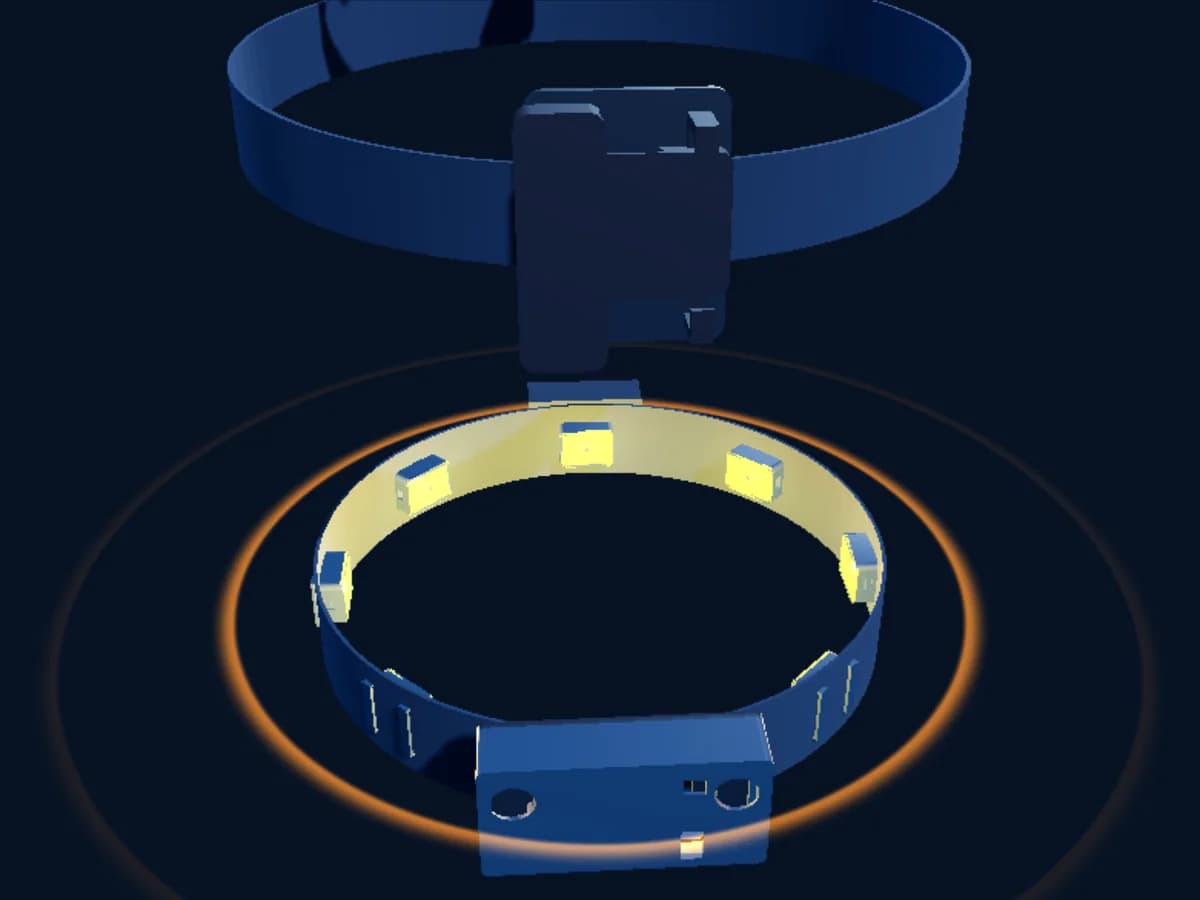
The second generation kit from its real part files: the belt with eight motor pods and the sensor pod at the front, the collar strip with four, two ankle bands with four each, with the belt speaking in amber.

Real now. The second generation design: its blueprint, its KiCad schematic and its printed part files, published below.

In development. The second generation hardware is being built and tested now, and is nearing MVP. Anything not yet measured on the bench is marked as a design value.

How it works

One hazard, world to skin.

Follow one doorframe through the whole kit: the light that finds it, the frame that carries it, the arithmetic that chooses a motor, the buzz that rises on the skin, and the step that clears it. Played to the modeled latency budget, then at real speed. Nothing here is a video; the numbers drive the drawing.

  1. World
  2. Sense
  3. Decide
  4. Feel
  5. Move


Forward laser grid, 4 by 4 at 60 Hz

01

World

the hazard

sensor frame, 25 ms

The pod's forward laser grid gathers one 4 by 4 frame at 60 Hz. Light leaves, hits the doorframe 0.6 m ahead at the right edge of the field, and comes back.

  • Wherethe right belt, because the right column is closest not yet
  • How strongstrong, because 0.6 m is close not yet
  • Motionno motion: nothing here is the ground not yet
65 degree diagonal field, to 400 cm in the dark, about 285 cm in daylight0.6 m4×416 DISTANCES, 60 HZCORAL = CLOSENEAREST PER COLUMNLEFTRight, 8 BELT MOTORSTALLER = CLOSER = STRONGER20 MOTORS, 0 BUZZING0%MOTOR RISEDRIVE AND RISE 20 + SKIN 150.6 mA wide berth

The modeled budget, true proportions

0 of about 70 ms, modeled

sensor frame 25
drive and rise 20
skin 15

Each stage holds on the stage long enough to be watched; the strip keeps the true proportions of the model, and the buzz and the sweep run at real speed. Every number is read from the same latency model and zone catalog the rest of this site uses, so this drawing cannot drift from the pages around it. The figure carries all 20 first-build motors from the catalog.

From the real files

The schematic, and the belt pod as it will be printed.

The belt hub schematic is a KiCad file in the repository, exported by kicad-cli, with an electrical rules check that returns zero at its default severities. The enclosures are OpenSCAD parts rendered by Blender: the belt pod, the motor pod, and the chest cradle. Nothing here is generated by a model; every dimension is a design value until a printed part is measured.

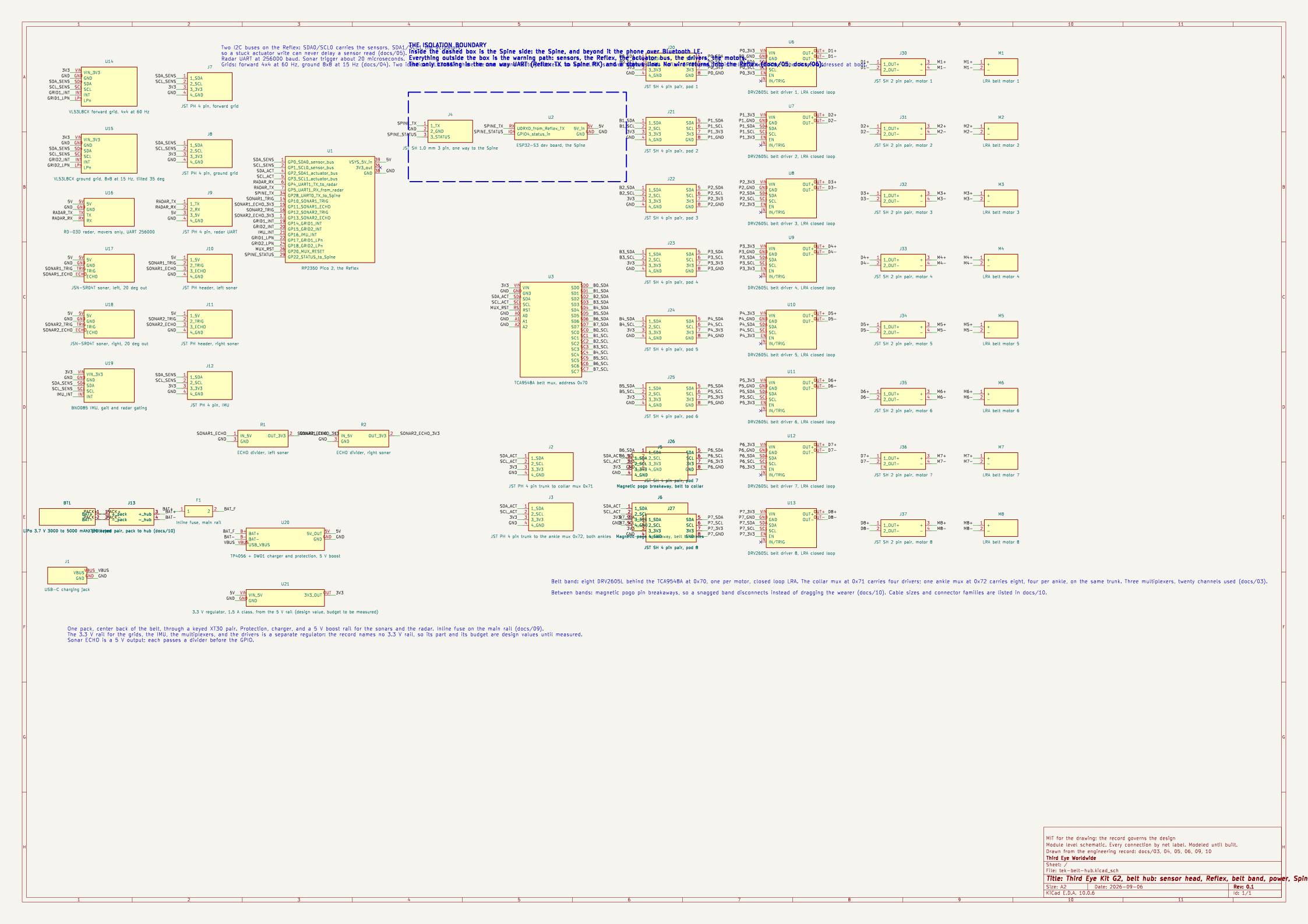
The belt hub schematic sheet: sensor modules on the left, the RP2350 Pico 2 in the center with its labeled pins, a dashed isolation boundary with the ESP32-S3 Spine to its right, the belt multiplexer and eight driver and motor pairs on the right, and the battery, fuse, charger and USB-C jack at the bottom left.
The belt hub schematic. Rendered by kicad-cli from the KiCad file in the repository: the two laser grids and the IMU on the Reflex's sensor I2C bus, the radar on its UART, the two sonars on trigger and echo lines; the belt multiplexer at 0x70 with its eight DRV2605L drivers and coin LRAs on the actuator bus; the trunk connectors and magnetic breakaways to the collar and ankle multiplexers; the pack, the fuse, the charger and the 5 V boost; and the one way link to the Spine across the isolation boundary. Every connection is a named net. kicad-cli's electrical rules check returns zero violations at its default severities. A module level schematic, modeled until built. Source: hardware/kicad/tek-belt-hub.kicad_sch, drawn from docs/03, 04, 05, 06, 09, 10.
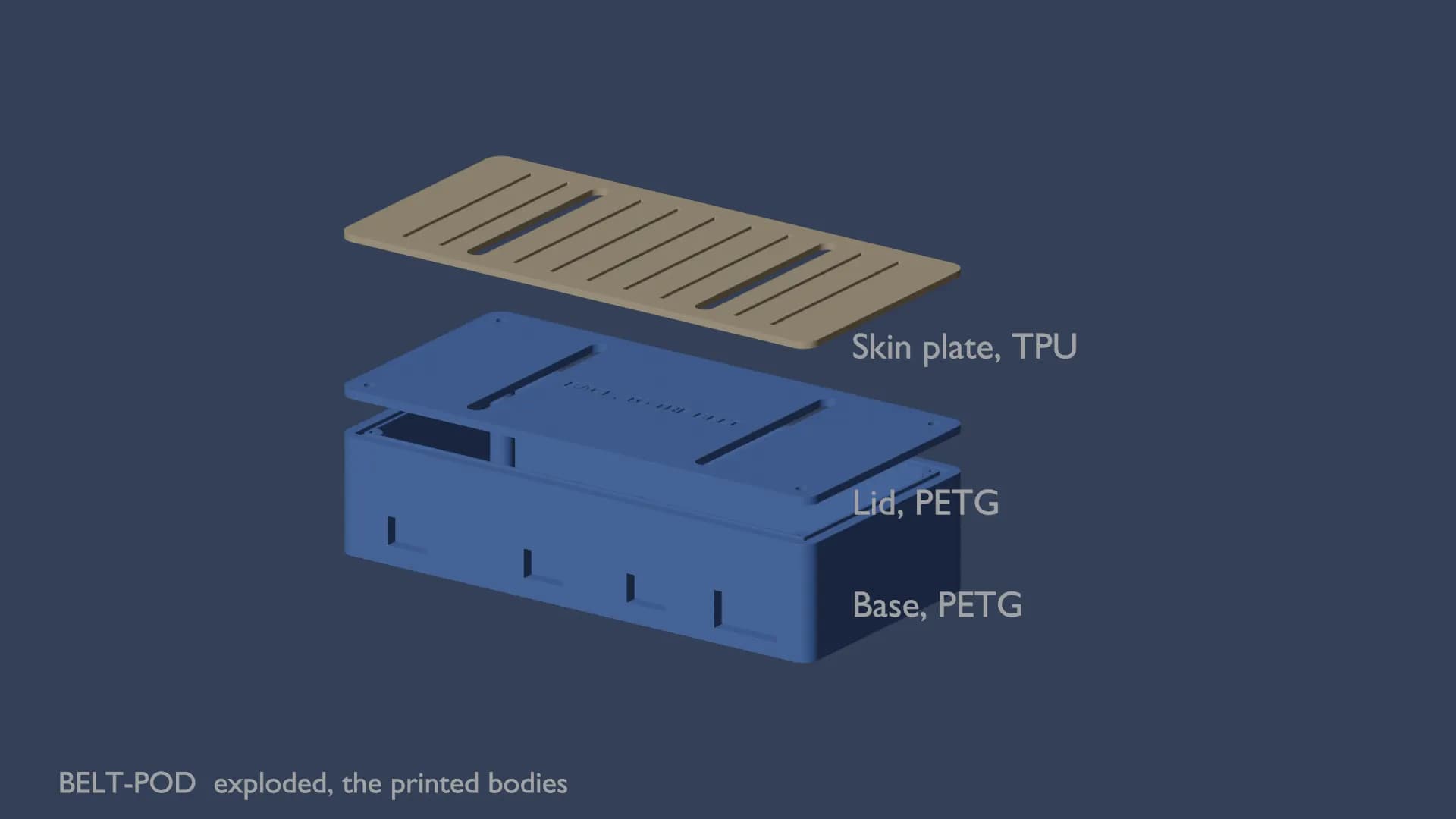
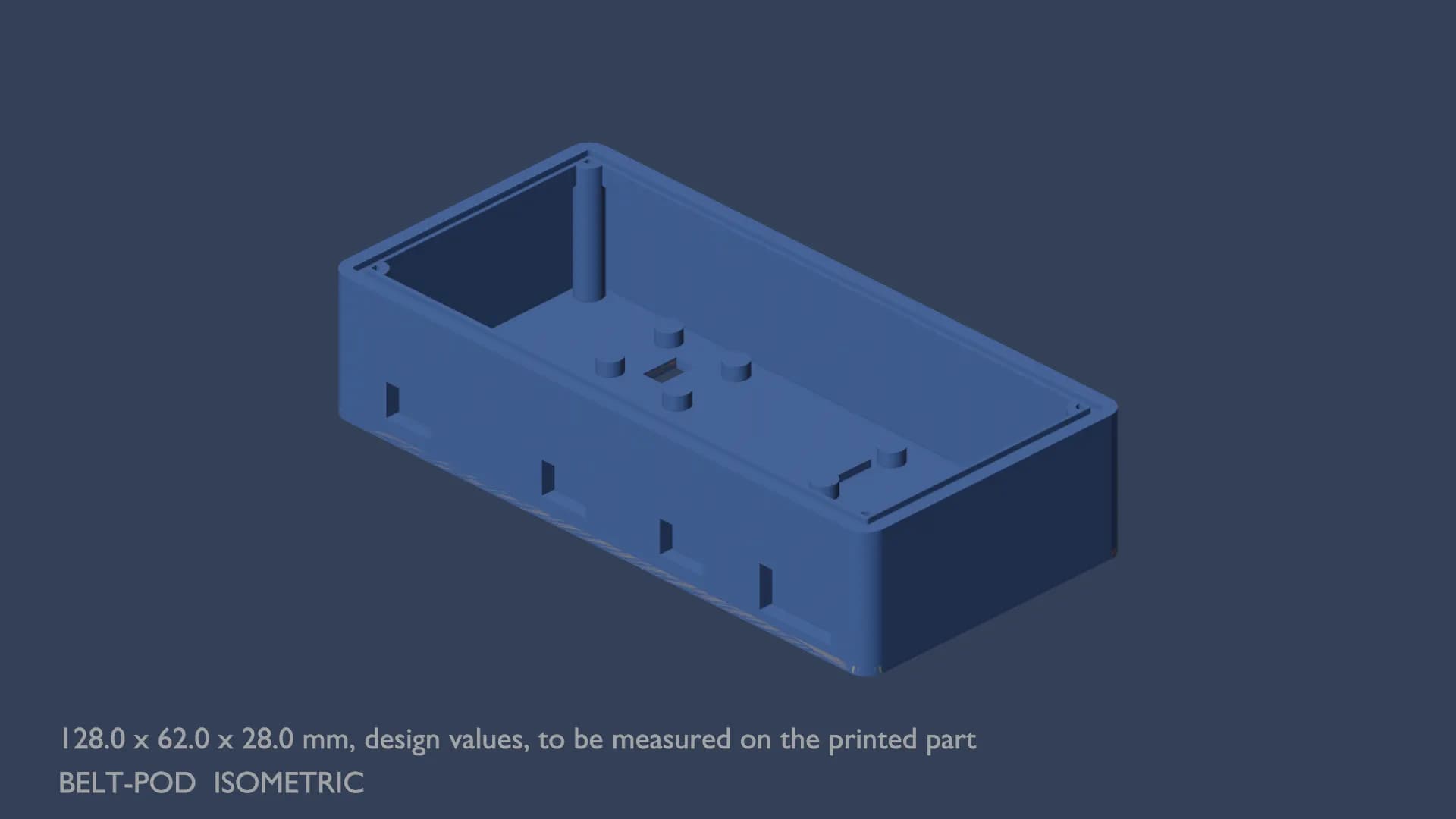
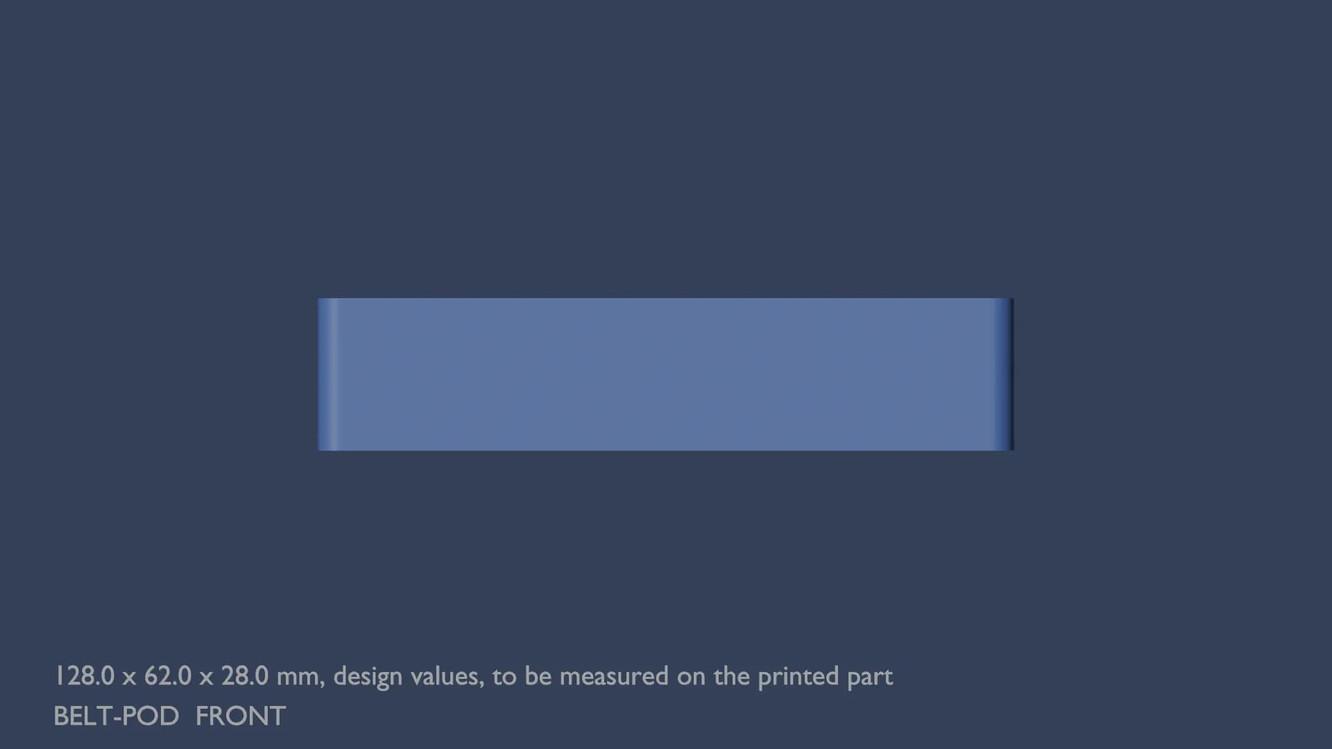
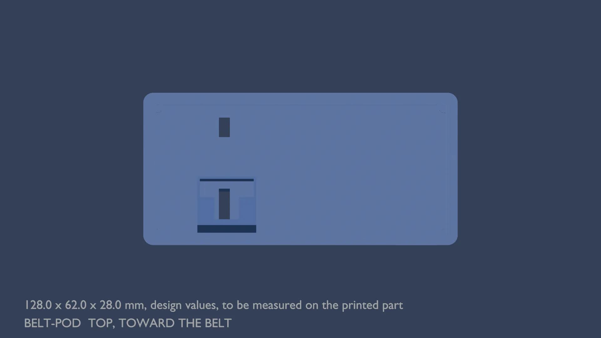
The belt pod: a rounded box the length of a hand, its three printed bodies lifted apart, the PETG base with sensor windows in its outward face, the PETG lid with two belt slots, and the soft TPU skin plate. Outer dimensions: base 128 by 62 by 28 mm, lid 128 by 62 by 2 mm, skin plate 128 by 62 by 1.6 mm, assembled 128 by 62 by 32.3 mm.Blueprint, isometric view of the belt pod with its outer dimensions written under it, design values to be measured on the printed part.Blueprint, front view of the belt pod.Blueprint, top view of the belt pod.
The belt pod. The sensor head and the electronics core in one shell: the forward and ground laser grids, the radar behind a half wave radome, 3.6 mm, a design value until measured, two sonars turned 20 degrees outward, the Reflex, the Spine, the belt multiplexer, and the charger, with a TPU skin plate toward the body. Outer dimensions, design values until a printed part is measured: base 128 by 62 by 28 mm, lid 128 by 62 by 2 mm, skin plate 128 by 62 by 1.6 mm, assembled 128 by 62 by 32.3 mm. Strain relief channels and service loops are not yet drawn; every enclosure dimension here is a design choice, not a measurement. Source: hardware/scad/belt-pod.scad, drawn from docs/04, 09, 10, 11.
Long description of the belt hub schematic

One A2 sheet. On the left, the sensor modules: the forward and ground VL53L8CX laser grids on the sensor I2C bus, each LPn on its own GPIO, the RD-03D radar on its own UART at 256000 baud on the 5 V rail, and the two JSN-SR04T sonars with their trigger lines and their ECHO lines divided down to 3.3 V logic. In the center, the RP2350 with every used pin labeled, its two I2C buses kept separate so a stuck actuator write can never delay a sensor read. A dashed isolation boundary runs to its right with one wire crossing it: the Reflex's TX into the ESP32-S3 Spine's RX, and nothing back. On the right, the belt multiplexer and the eight driver and motor pairs of the belt segment, each motor on a two pin connector, each driver pair on a four pin connector. At the bottom left, the battery, the inline fuse, the charger, and the USB-C jack. The electrical rules check returns zero at its default severities.

The KiCad source and the OpenSCAD parts open with the licence; the record provides no separate text netlist, so none is published yet.

The older drawings from the dossier and the first bench sketches are kept in the research archive.

Two generations, and what comes after the tests

Version 1, the first generation

The tested prototype

In use since 2022

  • Four AVR microcontrollers, one job each, in hard real time.
  • Ultrasonic ranging at the head, at both feet, and in the hand.
  • GPS and a 2G modem that text a family member the wearer's location.
  • We built and gave out tens of first generation kits ourselves. Because the design was open, hundreds more were built by the people who needed them, with our help sourcing parts.

What it was, what it got, where it went

Version 2, the second generation

The build

In build

  • 20 coin actuators in a belt, a collar strip, and two ankle bands.
  • Two laser grids, a radar, two sonars, and an IMU. About 70 ms from the world to the skin ahead, about 120 ms at the ground, modeled.
  • The Reflex and the Spine, with the hardware isolation boundary between them: a one way link from the Reflex to the Spine, and no wire back.
  • Five milestones, G0 to G4, before general use.

The build, from the record: architecture, sensors, parts, milestones

The assist frame, planned after the milestones

The braces

Planned

  • An exoskeleton for the legs and hips, planned after milestones G0 to G4.
  • Not built, not required, and not part of the second generation build. No actuator is on the parts list.
  • Assist frame work is considered only at the readiness review, after G0 to G3 pass.

The assist frame, as planned

Announcement

The brain moves to the phone.

The second generation drops the Jetson Orin Nano. The wearer's own smartphone, on a chest mount with its camera, carries the compute and the AI, and talks to the kit's Spine over Bluetooth; the Spine sits behind the one way link from the Reflex, so the phone can never write into the warning path. The microcontrollers, the drivers, and the little motors stay exactly where they are, in a loop that never waits on the phone.

The camera is the wearer's choice: the phone's own camera on the chest, a separate chest camera, or none at all. The warning bands work the same in every case.

The engineering record

Nineteen files. Every page traces to one of them.

The record in docs/ is the constitution of the second generation. If a fact is not in it, it is measured on the bench, or it stays off this site. Each file is rendered whole on its own page, with a figure drawn from its numbers.

  1. File 00Fixed facts and how to read this recordThis record is the constitution of the Third Eye Kit second generation. Every page of tek.sadeqi.me and every frame of the films traces to a file in docs/. If a fact is not here...
  2. File 01System overview and the three lawsTEK G2 is three body worn bands (waist belt, collar strip, two ankle bands) carrying 20 coin LRA actuators, a sensor head at the waist, a two processor electronics core, and the...
  3. File 02ActuatorsDecision: coin linear resonant actuator (LRA), 10 mm diameter, about 3.5 mm tall, resonant near 175 to 235 Hz, driven closed loop by the DRV2605L. Reference part Precision Micro...
  4. File 03Drivers and busDecision: one TI DRV2605L per motor in closed loop LRA mode, 20 drivers, grouped eight per TI TCA9548A I2C multiplexer, three multiplexers, on the actuator I2C bus of the Reflex...
  5. File 04Sensors and the fusion handoffsDecision: keep all four sensor families. Each owns a failure mode the others cannot cover.
  6. File 05The Reflex controllerSame price, near identical footprint, and it adds what the safety loop needs.
  7. File 06The Spine and T.E.K.-Link 0.1Decision: ESP32-S3 as the Spine for logging and Bluetooth LE to the phone, fed by the Reflex over a one way UART (Reflex TX to Spine RX, no wire back into the Reflex). The Spine...
  8. File 07The phone as the BrainDecision: the wearer's own smartphone on a chest mount is the Brain: camera, on device assistant and scene description, and the text home feature. It is out of the warning path.
  9. File 08The chest mount and the camera alternativeDecision: a quick release printed cradle on an elastic chest strap that shares the belt anchor so it does not pull. Holds the wearer's own phone in portrait or landscape with a...
  10. File 09PowerDecision: one central 3.7 V lithium polymer pack of 3000 to 5000 mAh, protected, mounted center back on the waist belt so its mass sits over the spine and does not pull the belt...
  11. File 10Wiring and connectorsBetween bands: magnetic pogo pin breakaway connectors, so a snagged band disconnects instead of dragging the wearer or tearing wire, and a wearer detaches a band without tools.
  12. File 11Bands, pods, and materialsSizing for 5th to 95th percentile adults (ANSUR II and NHANES class references; the general population runs larger than the military sample, so bias generous): - Waist: about 70...
  13. File 12Human limitsWeight: under 200 g per band; total on body electronics and bands, excluding the phone, about 700 to 900 g, and likely lower. Parts alone are under 100 g; the battery is about 1...
  14. File 13Safety and standards, and the TEK wearability standardOpen the file for the details.
  15. File 14End to end latency budget, modeled, with the measurement planThe motor is the pacing item. Measure its rise and brake time first. Every "modeled" phrase on the site switches to "measured" through one config value when the bench number exi...
  16. File 15Evaluation protocol, milestones G0 to G4Measures: contacts, veering (lateral deviation from a straight path), PPWS (course speed divided by preferred speed, Clark-Carter 1986; Soong 2000), walking speed. No single gol...
  17. File 16Prior art comparisonOpen the file for the details.
  18. File 17Bill of materials and the phone savingIt will change.
  19. File 18Corrections: where the current site is contradicted1. The home page says "About 1,000 sold and about 100 donated" and "About a thousand were sold and a hundred were given," with the hedge "by the founder's account." Replace ever...

The timeline

Two generations, in the open.

The dated record. It began at a blind support centre before 2022 with Said Mohaddes Sadeqi, was tested at TEKNOFEST 2022, was brought into use with blind and visually impaired people at that centre the same year, and was published whole. Every dated entry links to its source.

  1. BEFORE 2022, INTO USE IN 2022

    Born at a blind support centre.

    Said Mohaddes Sadeqi builds the first Third Eye Kit at the blind support centre where he was after losing his sight: ultrasonic ranging at the glasses and the shoes, warnings by sound and vibration, and a 2G text home to family with the wearer's location. He brings it to his school and enters TEKNOFEST 2022, Black Sea, in the Barrier-Free Living category under the team name ABRT01: finalist, and Best Presentation.

  2. SEPTEMBER 2022

    National coverage.

    Anadolu Agency reports on a student's third eye project for blind people. Faktor, in Bosnia and Herzegovina, also reports on the founder and the device he built.

  3. 2022 AND AFTER

    Field tests at the blind support centre.

    Two hardware revisions, demonstrated with blind and visually impaired people at the centre, whose feedback set the alert distances, feedback types, and fit. The first generation repository's ledger says what was and was not tried: near range alerts with blind users; crowds, traffic, and safety certification not.

  4. OCTOBER 2025

    The organization opens its site.

    The teww.org domain is registered on 14 October 2025 (public registry record; a date from outside the engineering record). The site carries the first-generation write-up and the second-generation spec.

  5. JULY 2026

    Both generations published.

    The first-generation repository is created on GitHub on 4 July 2026: spec, firmware, pinouts, bill of materials. The second-generation repository follows on 5 July 2026 (repository dates, from outside the engineering record): the dossier, the safety file, the four schematics. MIT for the code, CC BY 4.0 for the documents.

  6. NOW

    The second-generation build.

    The reference spec is frozen and the parts are on the bench. The brain tier moves from the Jetson to the wearer's own phone, on a chest mount, integrated with the microcontrollers across the isolation boundary. Bench drawings for the belt, the collar strip, and the ankle bands, the parts list, the placement study, and this engineering record. Firmware and assembly are the current work; the assist frame is planned after the tests.

Where this goes

Walk today. Run next.

The goal is the natural move: walking without bracing, then running, given back to blind and low-vision people. The tests measure it, walking speed and the percentage of preferred walking speed against a mobility aid only baseline, and running is not claimed until the test plan requires and verify it.

  1. Now

    Walk.

    The first build: a belt, a collar strip, and two ankle bands, six signals, a city block crossed by feel. Built for blind and visually impaired people; until the replacement test passes, keep traveling the way you travel now.

  2. Next

    Run.

    The architecture was built for speed. About 70 milliseconds from the world to your skin for what is ahead, modeled until the bench measures it: at 3 meters per second that is 21 centimeters of travel, which is acceptable, while the ground grid at 15 Hz sees a step edge only every 20 centimeters, which is tight. Running is not claimed until the test plan requires and verify it.

  3. Decided

    The phone is the brain.

    The wearer's own phone, on a chest mount with its camera, takes the work the dossier gave a Linux computer, at a fraction of the cost and weight (docs/07). The location text home that the first kit sent over a 2G modem rides in the phone: no modem, no SIM, no airtime to pay for, and nothing leaves the phone by default.

  4. After

    Whatever comes after.

    Our founder, Said Mohaddes Sadeqi, talks about skateboards. We are not sure yet, and we say so. We are sure we will find out, in the open, with the people this is for.

On the roadmap

TEK Reach. On the roadmap.

A small handle you hold like a flashlight and point ahead. It is an add-on to the kit, not part of it, and the belt keeps warning with or without it.

Sense. Point it at the space in front of you and the grip vibrates, stronger as something gets closer. Click it and your phone, or the glasses when they come, tells you what it is: a door, a bench, a person waiting.

Guide. Say what you are looking for, like "elevator button." The grip pulls your hand the way a friend would guide it, up or down in short pulses, left or right in a steady lean, and a clear double tap when you are there.

Research on vibration guidance for the hand gives us a place to start, and blind testers will tell us whether it works. Nothing here is built yet. When it is, it goes through its own testing milestone, published on the test plan like everything else.

Watch

The long videos.

The technical explainer

How the kit works inside: the sensors, the reflex controller, the motor drivers and the motors, and how one obstacle travels from the world to the skin.

Video not here yet. This full length video is being added to the site. Nothing plays here until the real recording is in place.

The front end view walkthrough

A guided walk through the front end view, step by step.

Video not here yet. This full length video is being added to the site. Nothing plays here until the real recording is in place.

How we work

Four habits.

  • Physics before AI

    Distance comes from lasers, radar, and sound. The AI reads signs and names things. It never steers.

  • Honest limits

    Status is stated plainly. Every page says what was measured and what was not.

  • Staged milestones

    Bench, controlled course, real routes, daily life, readiness review. Trial participants wear it from G1 under IRB, with an orientation and mobility specialist present and a trailing sighted guard; general use waits for G4, and assist frame work is considered only at the readiness review.

  • Open source

    Both generations live in public repositories. The firmware, the schematics, and the studies are on this site to read and to download.