I am blind or visually impaired: the story in one minute
Third Eye Kit

Engineering, version 2, second generation

The build.

Three body worn bands, a waist belt, a collar strip, and two ankle bands, carrying twenty coin actuators; a sensor head at the waist; a two processor electronics core; and the wearer's own smartphone on a chest mount. Distance to the world is measured, fused, and pressed onto the skin as vibration. No interpreter and no voice in the warning path.

THE RECORDCONSTITUTION
docs/00 to docs/18 are the single source of truth for this build. If a fact is not there, it is measured on the bench, or it stays off this site.
THE BUILDTO LEARN FROM
Belt, collar strip, two ankle bands, a sensor head at the waist, two processors, the wearer's own phone. Built to learn from, not to distribute yet.
THE ASSIST FRAMEPLANNED
Planned after milestones G0 to G4. Not built, not required, and not part of this build.

docs/00, Fixed facts and how to read this recorddocs/01, System overview and the three laws

Announcement

The brain moves to the phone.

The second generation drops the Jetson Orin Nano. The wearer's own smartphone, on a chest mount with its camera, carries the compute and the AI, and talks to the kit's Spine over Bluetooth; the Spine sits behind the one way link from the Reflex, so the phone can never write into the warning path. The microcontrollers, the drivers, and the little motors stay exactly where they are, in a loop that never waits on the phone.

The camera is the wearer's choice: the phone's own camera on the chest, a separate chest camera, or none at all. The warning bands work the same in every case.

Anyone, anywhere, can build this.

Our promise for the second generation: about three days of building, common parts, and a finished kit within about 10 days wherever you live. We are still testing it, and we will publish what a kit costs once the parts are final. The times are targets until builders outside our team time their own builds, and we will publish those times here.

Build time
about 3 days of buildingStatus: second generation target, being verified.
Finish anywhere
within about 10 days, including getting partsStatus: second generation target, being verified.
Parts cost
published once the parts are finalStatus: in testing.
First generation
built to be low cost from the startStatus: in use since 2022.
Steps
step count published with the second generation build guideStatus: pending.

The three-phase build path and the full parts list.

Architecture

Two processors and a phone, with a wall between them.

Sensors to the Reflex to drivers to motors is the warning path. The Reflex sends a one way copy of its state to the Spine, which talks to the phone over Bluetooth. The phone runs the camera, the assistant, and the text home, and can never write into the warning path.

THE WARNING path, sensors to skin, NO interpreter, no voice, no radioSENSORStwo laser grids, radar, two sonars, IMUTHE REFLEXRP2350, one hard real time loopDRIVERS20 DRV2605L behind 3 multiplexersMOTORS20 coin LRAs on the skinIsolation boundaryone way UART, Reflex TX to Spine RX, a copy of the state, no wire backThe spineESP32-S3, logging, Bluetooth LEBluetooth LEThe phonecamera, assistant, text homeThe phone never writes into the warning path.
The warning path and the boundary. Sensors feed the Reflex, the Reflex drives the motors, and nothing else is in that path. The Reflex sends a one way copy of its state across the isolation boundary to the Spine, which talks to the phone over Bluetooth. The phone runs the camera, the assistant, and the text home, and can never write into the warning path. Source: docs/01, docs/05, docs/06.

docs/01, System overview and the three lawsdocs/05, The Reflex controllerdocs/06, The Spine and T.E.K.-Link 0.1docs/07, The phone as the Brain

The three laws

Where it buzzes, how strong, and what moves.

The three laws do not change. Where it buzzes is where it would hit you. How strong is how close. If it moves, follow the motion. The first build speaks six signals: obstacle left, center, and right at the belt; head height at the collar; stairs up and stairs down at the ankles.

8

motors on the waist belt

anchored to the navel and the spine, where Cholewiak, Brill and Schwab found localization near perfect; about 92 percent correct with eight tactors around the torso

4

motors on the collar strip

one head channel, for anything at head height

4 + 4

motors on the ankle bands

four per readable stroke: a sweep up means stairs up, a sweep down means stairs down

30 mm

trunk spacing

the trunk spacing the record's placement sources set

docs/01, System overview and the three laws

Actuators and drivers

Twenty coin motors, one driver each.

Coin linear resonant actuators, 10 mm across and about 3.5 mm tall, resonant at the lower edge of the band where the skin is most sensitive, each driven closed loop by its own DRV2605L. The drivers sit eight to a multiplexer on the Reflex's actuator bus. A pod or a driver is a plug replaceable module.

100 Hz150 Hz200 Hz250 Hz300 Hz350 Hz400 HzPacinian channel, most sensitive 200 to 300 Hz, peak near 250LRA 175 to 235 Hzrise to rated amplitude37 msstop, with DRV2605L braking35 to 50 msnatural stop, no braking177 msReference part Precision Microdrives C10-100; second source Vybronics VG1040003D, about 10 ms to half amplitude. Measured at the skin through the band liner before any perceptual claim.
Why a linear resonant actuator, and where it parks its energy. The Pacinian channel is most sensitive from 200 to 300 Hz with its peak near 250 Hz. A coin LRA resonates near 175 to 235 Hz, at the lower edge of that band, 175 Hz for the reference part, driven closed loop by the DRV2605L. The reference part rises to rated amplitude in about 37 milliseconds and stops in about 35 to 50 with braking, against 177 unbraked. An ERM couples frequency to amplitude, so stronger also means a different pitch, which blurs the second law, and it rises and brakes slowly, which blurs the third. Source: docs/02.
The reflexactuator I2C bus, 400 kHzSDA1 / SCL1TCA9548A0x70, belt, 8 of 8 channelsTCA9548A0x71, collar, 4 of 8 channelsTCA9548A0x72, both ankles, 8 of 8 channelsEach small box is a DRV2605L at 0x5A on its own channel, closed loop LRA mode; each disc is a coin LRA. Twenty in all.
Twenty drivers behind three multiplexers. The DRV2605L address is fixed at 0x5A, so twenty identical drivers cannot share one bus. The record groups them eight channels to a TCA9548A multiplexer, three multiplexers on the Reflex's actuator bus at addresses from 0x70. The split drawn here, the belt's eight on 0x70, the collar's four on 0x71, both ankles' eight on 0x72, is the schematic's design allocation, not fixed by the record. A motor pod or a driver is a plug replaceable module. An amplitude write over I2C at 400 kHz takes well under a millisecond; refreshing all twenty fits inside one control tick. Source: docs/03.

docs/02, Actuatorsdocs/03, Drivers and bus

The sensing stack

Four sensor families. Each owns a failure the others cannot cover.

Two laser grids, a radar, two sonars, and an IMU. The laser grid owns the near field and drop offs; sonar owns glass and large surfaces; radar owns movers only; the IMU milestones the radar and reads gait. No single sensor is trusted alone, and the camera is never in the warning path.

0 cm5 cm25 cm60 cm1 m2 m4 m8 mThe skin8 MLASER GRIDowns 5 to 60 cm; shape and drop offs beyond, at lower confidence; 65 degree diagonal field; 400 cm dark, about 285 cm daylightSONARowns glass and large surfaces, 25 cm to 4 m; blind zone under about 25 cm sits inside the belt line; two, angled 20 degrees outRADARowns movers only, to 8 m; three tracks; it cannot range what does not move; the IMU says when the wearer has stoppedan object, approachingDisagreement rule: grid sees nothing, sonar sees a surface, buzz.
Who owns what, from eight meters to the skin. Each sensor family owns a failure mode the others cannot cover. The laser grid owns five to sixty centimeters, sonar owns glass and large surfaces from twenty five centimeters to four meters, radar owns movers only out to eight meters. When the grid sees nothing and the sonar sees a surface, the kit buzzes: a false buzz costs a step, a missed glass door costs a face. Thin poles are caught by running the grid at 8 by 8 every fourth frame. Source: docs/04.
  • Forward laser grid

    STMICRO VL53L8CX

    GRID
    4 by 4 at 60 Hz, one 8 by 8 frame every fourth cycle
    FIELD
    65 degrees diagonal
    REACH
    400 cm dark, about 285 cm daylight
    LIGHT
    940 nm Class 1 VCSEL
    Owns
    5 to 60 cm, plus shape and drop offs beyond at lower confidence.
    Misses
    Glass. Bright sun shortens its reach.
  • Ground laser grid

    STMICRO VL53L8CX, TILTED DOWN ABOUT 35 DEGREES

    GRID
    8 by 8 at 15 Hz
    JOB
    ground shape, curbs, drop offs
    Owns
    The ground ahead of the leading foot.
    Misses
    At 15 Hz it sees a step edge only every 20 cm at a run.
  • Radar

    AI-THINKER RD-03D, 24 GHZ FMCW

    TRACKS
    up to three, to 8 m
    FIELD
    plus or minus 60 degrees azimuth, plus or minus 30 elevation
    LINK
    UART, 256000 baud
    POWER
    5 V at 200 mA
    Owns
    Movers only: people, bikes, carts. By design.
    Misses
    Anything that is not moving. The IMU says when the wearer has stopped and the radar is trusted less.
  • Sonar

    TWO JSN-SR04T, 40 KHZ, WATERPROOF

    REACH
    about 25 cm to 450 cm
    BLIND ZONE
    about 20 to 25 cm, placed inside the belt line
    ANGLE
    two, about 20 degrees outward
    TRIGGER
    about 20 microseconds
    Owns
    Glass and large surfaces, 25 cm to 4 m. Firmware takes the nearest valid echo.
    Misses
    Small or sharply angled targets.
  • IMU

    CEVA BNO085

    AXES
    9, with on chip fusion
    RATE
    rotation vector to 400 Hz
    Owns
    Gating the radar; detecting gait and a running pace.
    Misses
    Nothing in the world; it watches the wearer.

docs/04, Sensors and the fusion handoffs

The reflex, the spine, the boundary

One loop that never waits, and a wire that goes one way.

The Reflex is an RP2350: dual Cortex-M33 at 150 MHz with hardware float, 520 kB of SRAM, signed boot, and a hardware watchdog. It reads, fuses, applies the three laws, writes the motors, and services the watchdog every tick. The Spine is an ESP32-S3 fed by a one way UART; it logs and talks to the phone. Twenty bytes per tick cross the wire.
READboth grids on the sensor I2C bus, the radar on UART, the IMUFUSEa per column nearest distance mapthe handoffs of docs/04DETECTdrop offs from the ground gridmovers from the radarTHREE LAWStwenty amplitude and rhythm commandsWRITEthe twenty commands through the actuator I2C busWATCHDOGserviced every tickbrownout or a missed tick resets to all motors offevery tick, then again. The RP2350's hardware float runs the fusion; signed boot protects the firmware; brownout and watchdog reset to a safe state.
One loop, two buses, nothing upstream can block it. The Reflex reads, fuses, applies the three laws, writes the motors, and services the watchdog every tick. Two I2C buses keep a stuck actuator write from ever delaying a sensor read. The Reflex has no data dependency on the Spine or the phone; it only transmits. Source: docs/05.
SYNCbyte 0VERbyte 1SEQbyte 2FLAGSbyte 3COLS, eight belt columnsbytes 4 to 11HEADbyte 12GNDbytes 13 to 14MOVERbytes 15 to 16AMPLbyte 17STATEbyte 18CRC8byte 19Offsets in bytes. One frame per control tick; at twenty bytes it fits a Bluetooth notify with room to spare, and the phone link's tens of milliseconds never touch the warning path.
T.E.K.-Link 0.1, twenty bytes per tick. A sync byte, the version 0x01, a rolling counter, flag bits for drop off, mover present and faults, eight belt column distances, the collar distance, the ground and drop off state, the nearest mover's range and bearing, an amplitude summary, the state machine code, and a CRC8 over the first nineteen bytes. Little endian. The team's own format, not a standard. Source: docs/06.
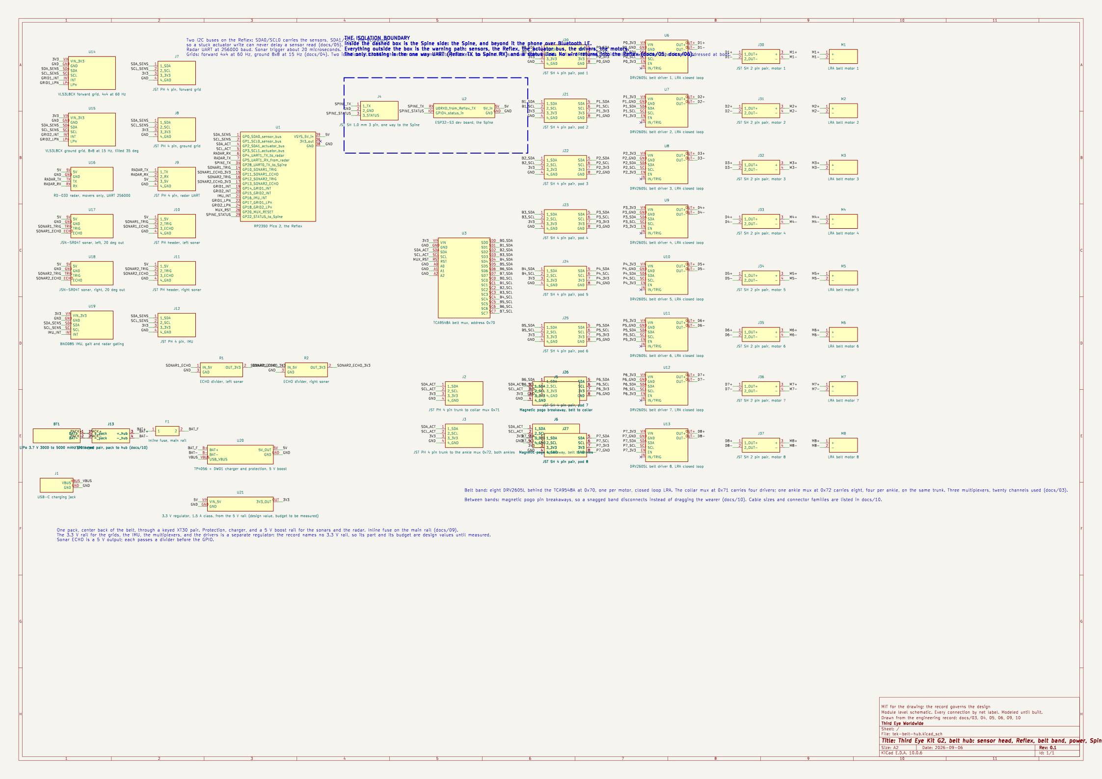
The belt hub schematic sheet: sensor modules on the left, the RP2350 Pico 2 in the center with its labeled pins, a dashed isolation boundary with the ESP32-S3 Spine to its right, the belt multiplexer and eight driver and motor pairs on the right, and the battery, fuse, charger and USB-C jack at the bottom left.
The belt hub schematic. Rendered by kicad-cli from the KiCad file in the repository: the two laser grids and the IMU on the Reflex's sensor I2C bus, the radar on its UART, the two sonars on trigger and echo lines; the belt multiplexer at 0x70 with its eight DRV2605L drivers and coin LRAs on the actuator bus; the trunk connectors and magnetic breakaways to the collar and ankle multiplexers; the pack, the fuse, the charger and the 5 V boost; and the one way link to the Spine across the isolation boundary. Every connection is a named net. kicad-cli's electrical rules check returns zero violations at its default severities. A module level schematic, modeled until built. Source: hardware/kicad/tek-belt-hub.kicad_sch, drawn from docs/03, 04, 05, 06, 09, 10.

docs/05, The Reflex controllerdocs/06, The Spine and T.E.K.-Link 0.1

The phone as the brain

The camera and the AI live in the wearer's own phone.

Qualifying phones run scene description, obstacle labeling, the assistant's routine dialog, and the text home on device and offline: iPhones with Apple Intelligence on iOS 26 or later, and Android 14 or later devices with AICore and Gemini Nano. Older phones still run the app for logging and the text home. Cloud APIs are optional, opt in, online only. The phone receives only the Reflex's one way state copy through the Spine and can never write back, and the belt keeps working regardless of phone battery.
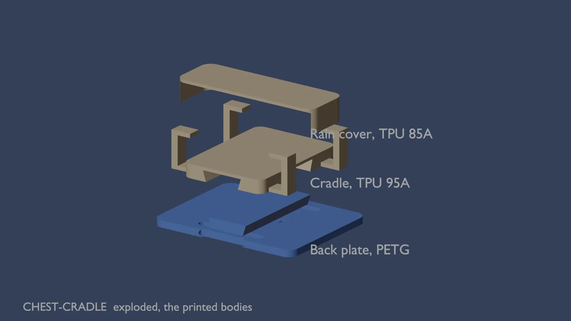
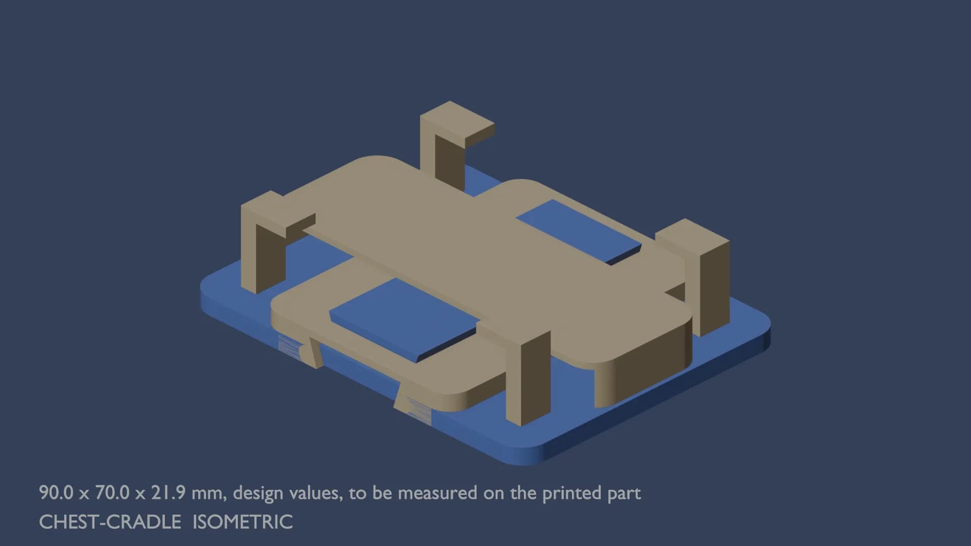
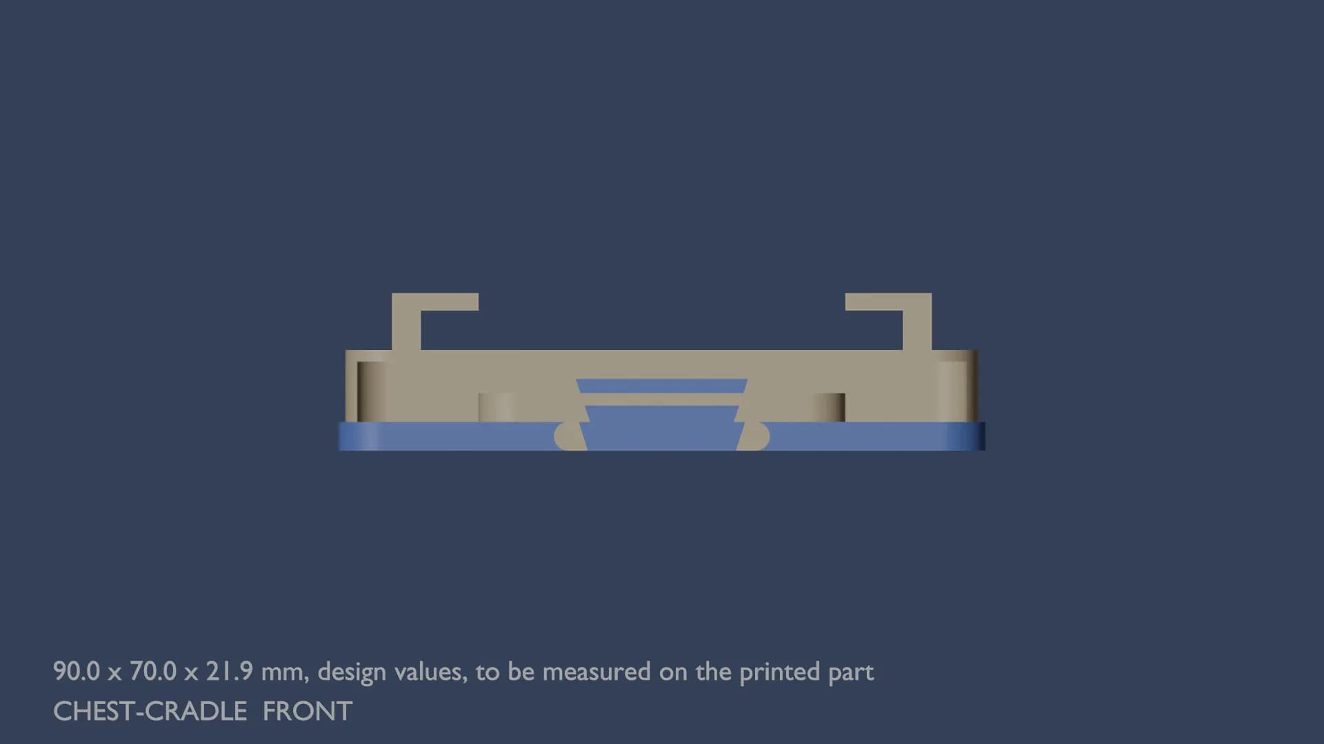
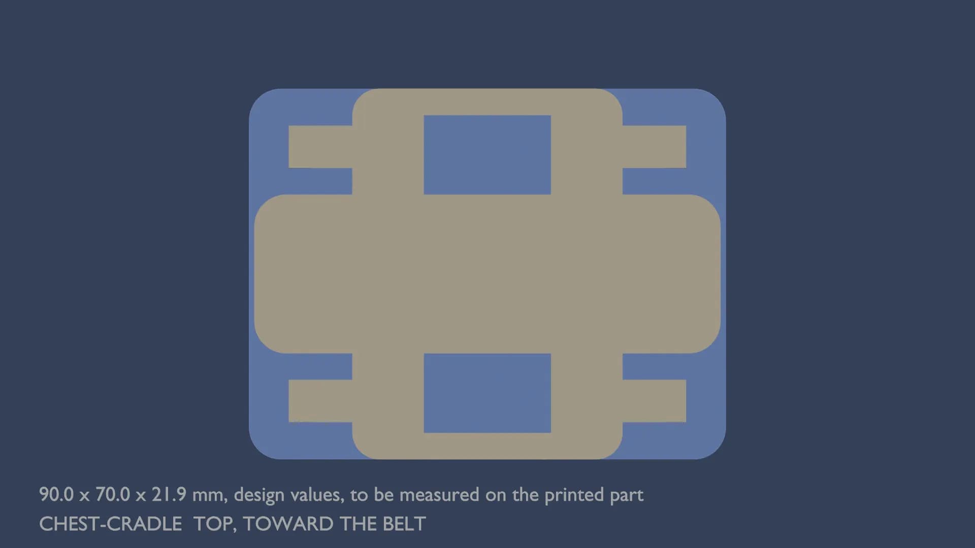
The chest cradle: a back plate with strap slots and a dovetail rail, the soft cradle with four spring jaws, and the rain cover, lifted apart. Outer dimensions: back plate 90 by 70 by 10 mm with its rail, cradle 75 by 70 by 21.9 mm with its jaws, rain cover 88 by 30 by 14 mm.Blueprint, isometric view of the chest cradle with its outer dimensions written under it, design values to be measured on the printed part.Blueprint, front view of the chest cradle.Blueprint, top view of the chest cradle.
The chest cradle, from the OpenSCAD part. A quick release printed cradle on an elastic chest strap that shares the belt anchor so it does not pull. It holds the wearer's own phone, portrait or landscape, with a rain cover option; a compliant TPU face absorbs breathing and bounce. Wireless to the Spine, so there is no cable to snag. For a wearer who cannot spare a phone, a low cost camera module driven by the Spine clips into the same mount. Outer dimensions, design values until a printed part is measured: back plate 90 by 70 by 10 mm with its rail, cradle 75 by 70 by 21.9 mm with its jaws, rain cover 88 by 30 by 14 mm. Strain relief channels and service loops are not yet drawn; every enclosure dimension here is a design choice, not a measurement. Source: hardware/scad/chest-cradle.scad, drawn from docs/08 and docs/11.

docs/07, The phone as the Braindocs/08, The chest mount and the camera alternative

Power

One pack, center back.

A protected 3.7 V lithium polymer pack of 3000 to 5000 mAh, a charger and protection module, a 5 V boost rail for the sonars and the radar, USB-C charging in a few hours, an inline fuse, a keyed connector. Runtime is a full waking day at typical duty and several hours at worst case, both to be measured.

THE PACK3.7 V LiPo, 3000 to 5000 mAh, protected, center backFUSEinline, main railCHARGER + PROTECTIONTP4056 and DW01 class, or one PMIC; USB-C in5 V BOOST RAILradar, two sonars; the Reflex supply is a design value3.3 V LOGIC RAILgrids, IMU, multiplexers, drivers: regulator and budget to be measuredUSB-C, chargeSAFETY: OVERCHARGE, OVER DISCHARGE, SHORT CIRCUIT protection, keyed, polarity cannot reverse
One pack, one fuse, two rails. A protected 3.7 V lithium polymer pack of 3000 to 5000 mAh, mounted center back on the belt so its mass sits over the spine. Charger and protection, USB-C charging in a few hours, an inline fuse on the main rail, a keyed connector, and a 5 V boost rail for the sonars and the radar. IEC 62133-2 and UN 38.3, the battery use and transport certifications, are required before any kit ships (docs/13), in hand at G0, not yet passed. The record names no 3.3 V rail: the logic supply for the grids, the IMU, the multiplexers, and the twenty drivers, its regulator and its current budget, is a design value to be measured. Runtime is to be measured, not assumed. Source: docs/09.

docs/09, Power

Wiring and connectors

Every plug named.

Motor to driver, driver to multiplexer, multiplexer to Reflex, sensors to Reflex, Reflex to Spine, Spine to phone, battery to everything, and the magnetic breakaways between bands. Each has a named cable and a named connector, so a field repair is a swap.

LINKCABLECONNECTORNOTEMotor to driver30 AWG twisted pair, siliconeJST SH 1.0 mm, 2 pininside the pod, strain relieved at the pod wallDriver to multiplexer28 AWG, 4 conductorJST SH 1.0 mm, 4 pinone run per band segmentMultiplexer to Reflex26 AWG, 4 conductor, shieldedJST PH 2.0 mm, 4 pinthe trunk backboneSensors to Reflex26 AWGJST PH 2.0 mm, 4 pin; sonar keeps its captive cablesensor bus separate from actuator busReflex to Spine28 AWG, 3 conductorJST SH 1.0 mm, 3 pinone way, no RX into the ReflexSpine to phonewirelessnoneBluetooth LEBattery to everything24 AWG silicone main railkeyed JST PH 2.0 mm or XT30inline fuseBetween bandsthe trunkmagnetic pogo pin breakawaya snagged band disconnects instead of dragging the wearer
Every link, its cable, and its plug. Eight links carry the kit. Each has a named cable and a named connector, so a pod, a driver, or a band is a plug replaceable module and a field repair is a swap, not a solder. Between bands the trunk passes through magnetic pogo pin breakaways. Routing runs in a fabric channel sewn to the inside of each band, away from the skin; pods are gasketed to IP54 class. Source: docs/10.

docs/10, Wiring and connectors

Bands, pods, materials

Sized for real bodies, printed in skin safe plastics.

Breathable elastic webbing with a soft liner, hook and loop plus a cam buckle, PETG or nylon pods with certified skin safe TPU faces. The belt pod carries the sensor head and the electronics core; twenty motor pods carry one coin LRA and its driver each; the pack sits center back.
20 cm40 cm60 cm80 cm100 cm120 cm140 cmWaist belt70 to 130S, M, L, XL, each with 15 to 20 cm of elastic and hook overlapChest strap80 to 120two sizes with adjustmentCollar strip32 to 45one size with adjustmentAnkle bands20 to 28one size with a wide hook and loop range
Sized for the 5th to 95th percentile adult. ANSUR II and NHANES class references, biased generous because the general population runs larger than the military sample. Bands are breathable elastic webbing with a soft brushed liner and hook and loop plus a cam buckle. Pods are PETG or nylon with a certified skin safe TPU face; textiles in prolonged skin contact meet OEKO-TEX STANDARD 100 Class II; skin contact plastics pass ISO 10993-5 and 10993-10. Source: docs/11.
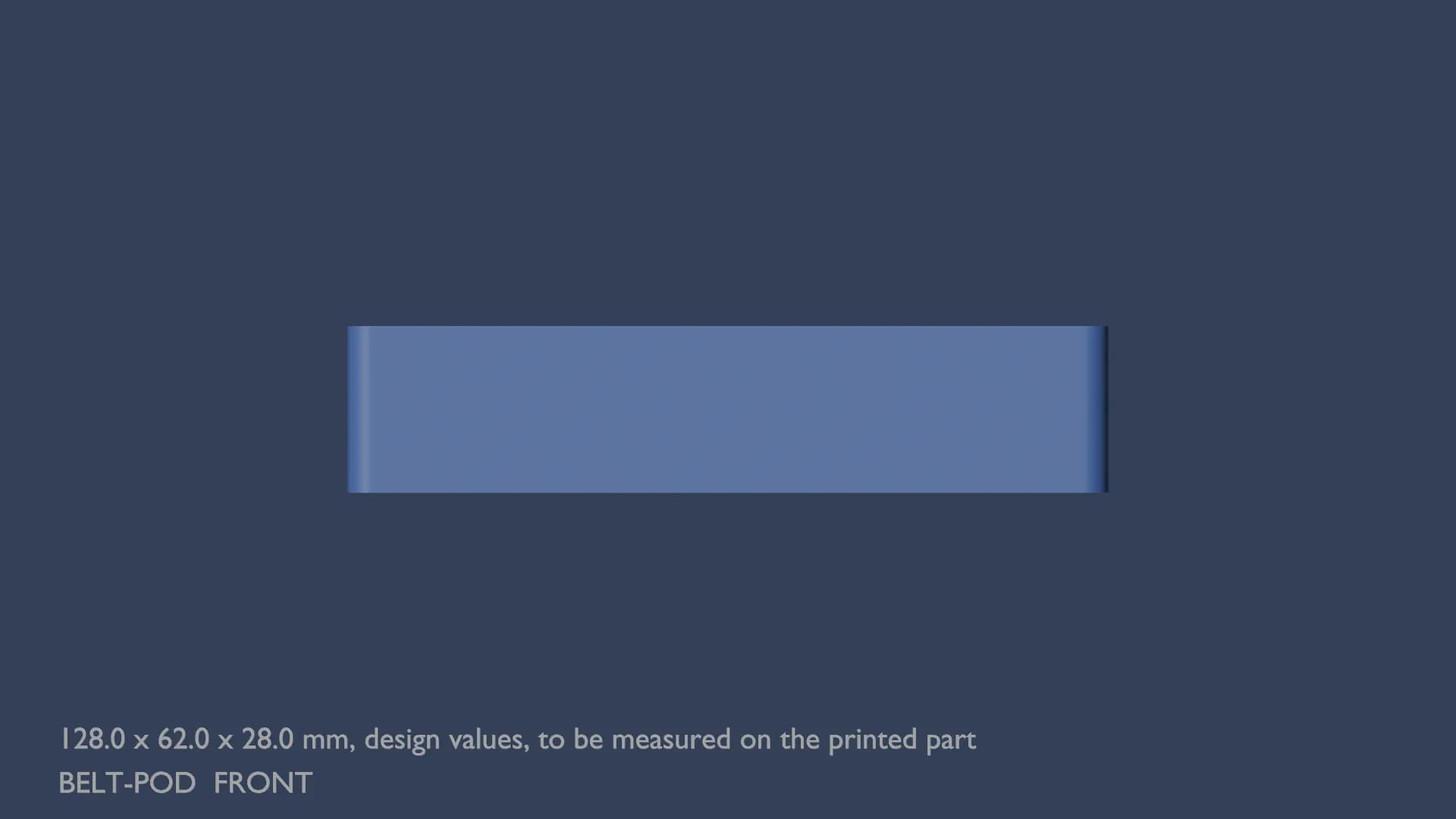
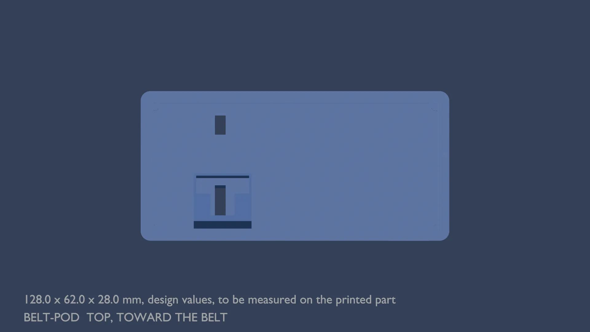
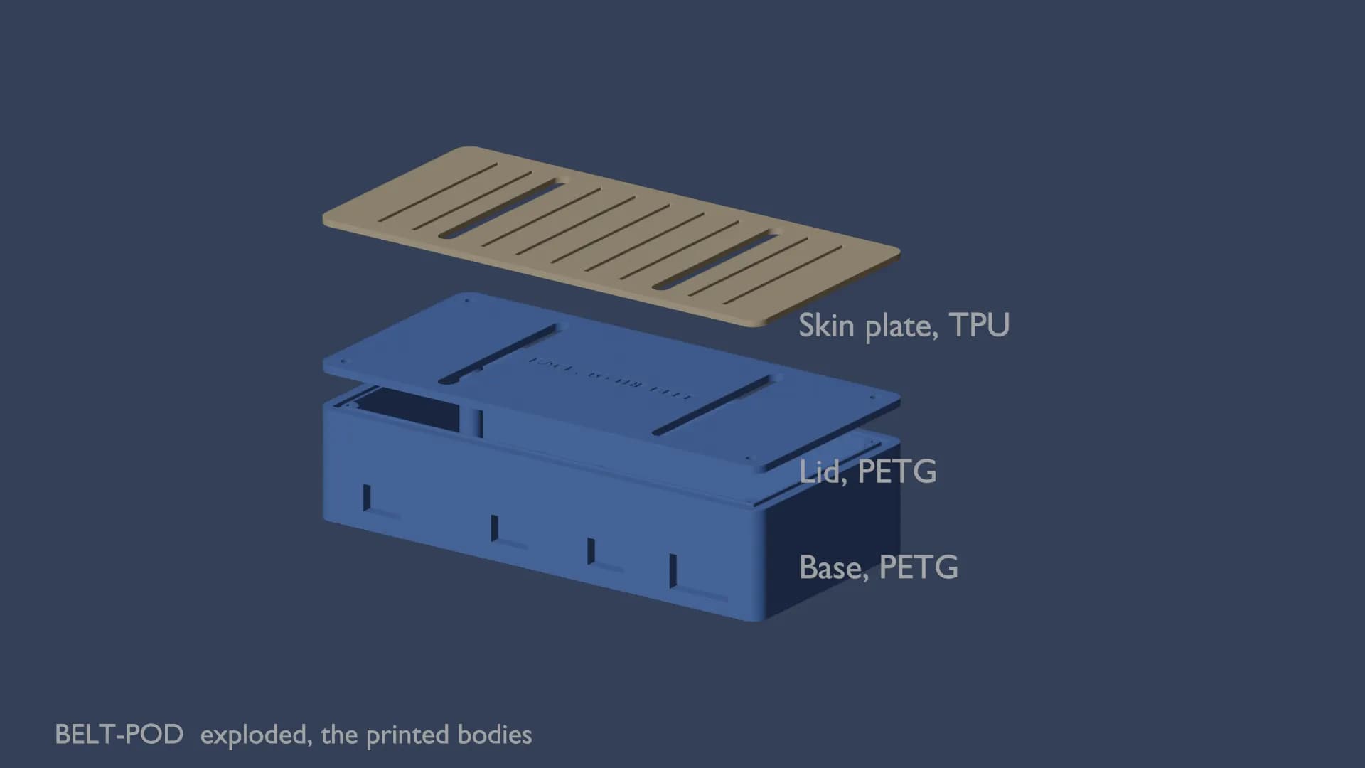
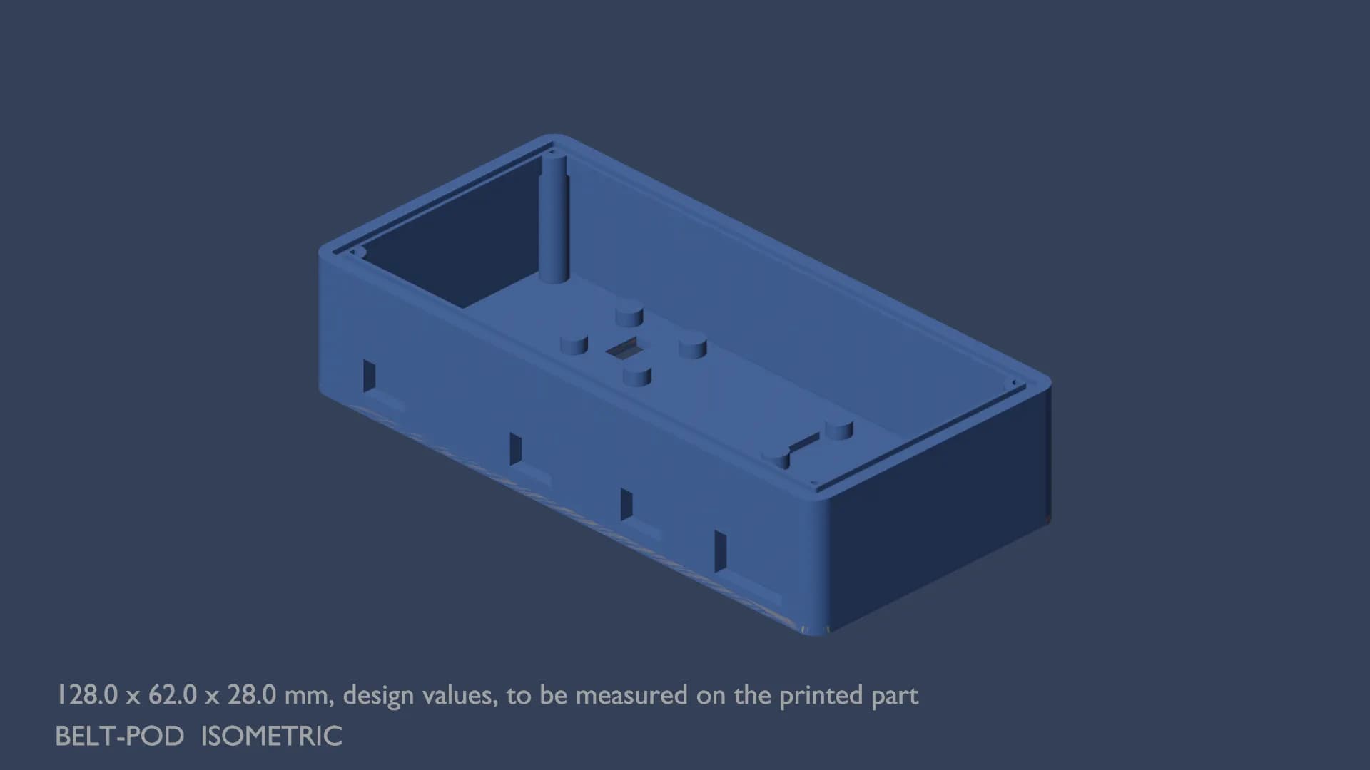
The belt pod: a rounded box the length of a hand, its three printed bodies lifted apart, the PETG base with sensor windows in its outward face, the PETG lid with two belt slots, and the soft TPU skin plate. Outer dimensions: base 128 by 62 by 28 mm, lid 128 by 62 by 2 mm, skin plate 128 by 62 by 1.6 mm, assembled 128 by 62 by 32.3 mm.Blueprint, isometric view of the belt pod with its outer dimensions written under it, design values to be measured on the printed part.Blueprint, front view of the belt pod.Blueprint, top view of the belt pod.
The belt pod, from the OpenSCAD part. The sensor head and the electronics core in one PETG shell, a PETG lid toward the belt, and a TPU skin plate against the body. The outward face carries every sensor window: the forward laser grid, the ground grid on a 35 degree wedge, a half wave radome for the radar, 3.6 mm, a design value until measured, and two sonar openings turned 20 degrees outward. Module outlines inside are working figures to be checked against the parts in hand. Outer dimensions, design values until a printed part is measured: base 128 by 62 by 28 mm, lid 128 by 62 by 2 mm, skin plate 128 by 62 by 1.6 mm, assembled 128 by 62 by 32.3 mm. Strain relief channels and service loops are not yet drawn; every enclosure dimension here is a design choice, not a measurement. Source: hardware/scad/belt-pod.scad, drawn from docs/04, 09, 10, 11.
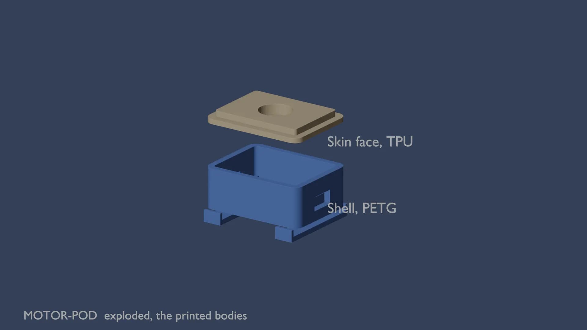
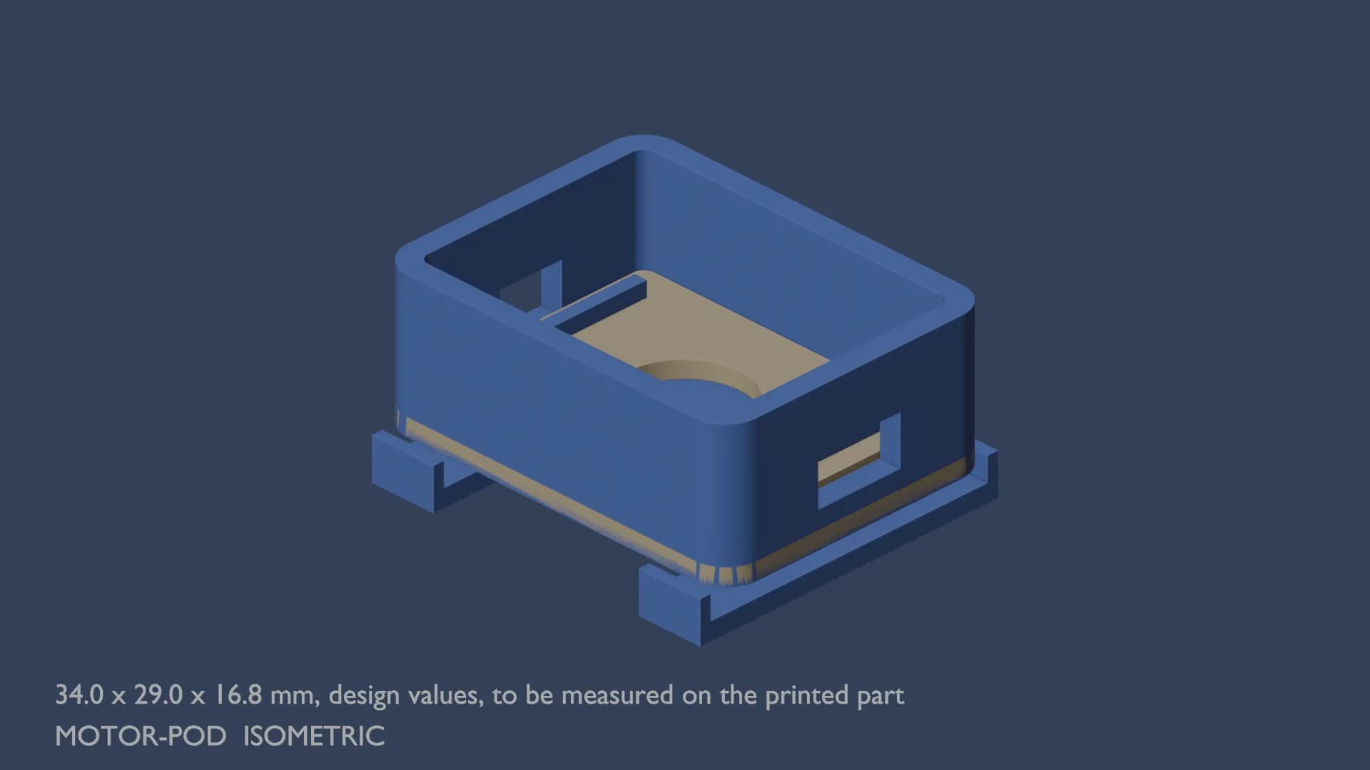
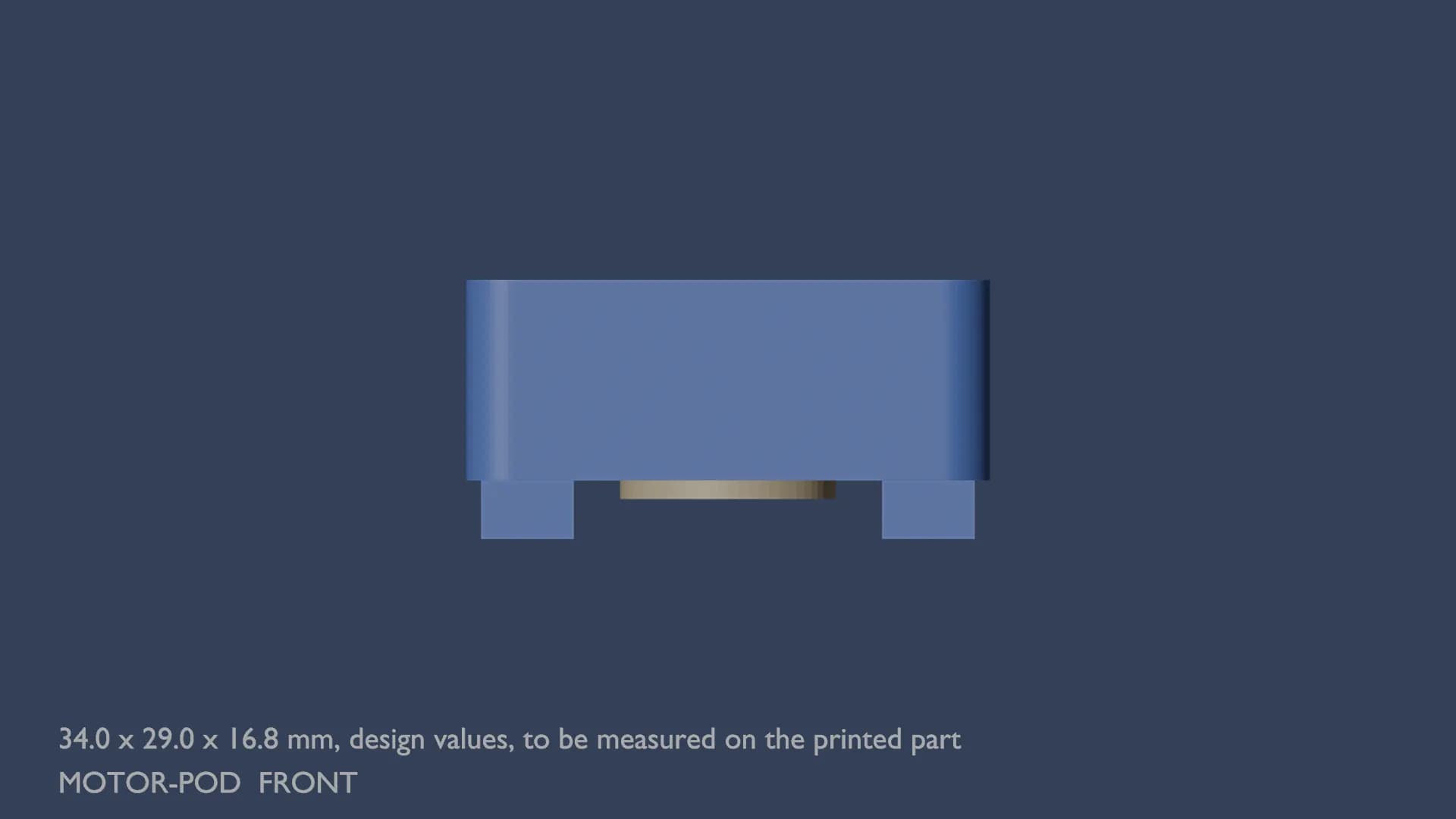
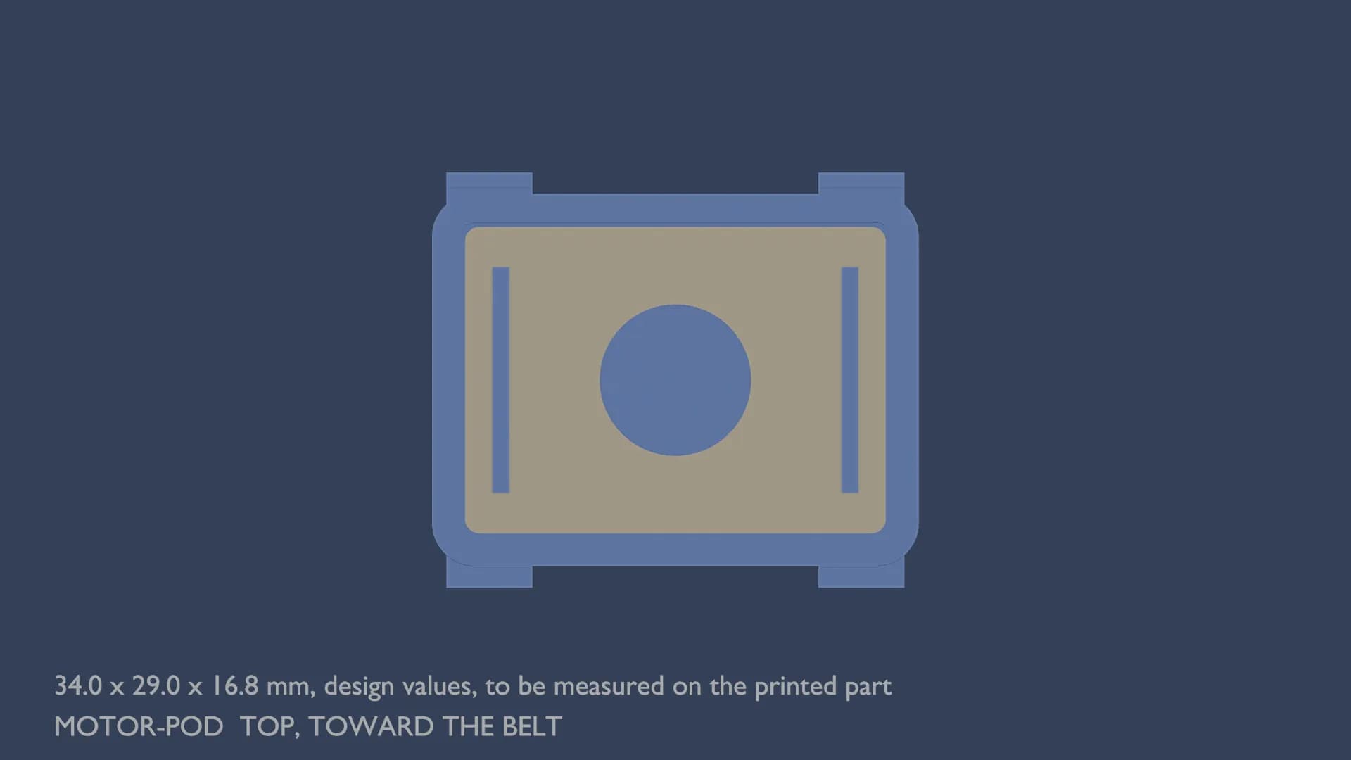
The motor pod: a small rounded shell for the driver board with two webbing loops, and the soft TPU face with a raised seat for the coin motor, lifted apart. Outer dimensions: shell 34 by 29 by 16.8 mm with its webbing loops, face 34 by 26 by 4.8 mm with its motor seat, assembled 34 by 29 by 18 mm.Blueprint, isometric view of the motor pod with its outer dimensions written under it, design values to be measured on the printed part.Blueprint, front view of the motor pod.Blueprint, top view of the motor pod.
The motor pod, from the OpenSCAD part. Twenty per kit. A small PETG shell holds the DRV2605L board and two webbing loops; the TPU face carries the coin LRA in a raised seat so it presses on the skin through the band liner. Motor lead JST SH 2 pin, bus JST SH 4 pin. Outer dimensions, design values until a printed part is measured: shell 34 by 29 by 16.8 mm with its webbing loops, face 34 by 26 by 4.8 mm with its motor seat, assembled 34 by 29 by 18 mm. Strain relief channels and service loops are not yet drawn; every enclosure dimension here is a design choice, not a measurement. Source: hardware/scad/motor-pod.scad, drawn from docs/02, 03, 10, 11.

docs/11, Bands, pods, and materials

Human limits

Weight, heat, wear time, running.

Under 200 grams per band, about 700 to 900 grams on the body without the phone. A rest after about two hours of continuous wear. Running is not claimed until the test plan requires and verify it.

On body weight, no phoneparts under 100 gbattery about 100 gbands, pods, cables, mount: the rest, about 500 to 700 g if the parts run to their 100 g bound, of a 700 to 900 g totalPer band: under 200 g. Rest after about 2 hours of continuous wear; a full waking day as the daily limit; per wearer amplitude calibration planned for older adults.RUNNING, 3 M PER SECOND21 cm of travel in the 70 ms world to skin time20 cm between ground grid frames at 15 Hz: tightRunning mode, gated by the IMU: scene description pauses, ground grid priority rises, only the reflex belt runs. Not claimed until verified.
What a wearer feels is not weight. Under 200 grams per band and about 700 to 900 grams on the body without the phone, likely lower: parts under 100 grams, the battery about 100, the rest bands, pods, cables, and the mount. Nobody feels that weight; they feel heat, sweat, chafe, and strap migration. A rest after about two hours of continuous wear and a full waking day as the daily limit, until measured on real wearers. At a running pace of 3 meters per second, 70 milliseconds is 21 centimeters of travel, while the 15 Hz ground grid sees a step edge only every 20 centimeters, which is tight; running is not claimed until the test plan requires and verify it. Source: docs/12.

docs/12, Human limits

The latency budget

About 70 milliseconds ahead, about 120 on the ground. Modeled.

Five stages from the sensor's exposure to the skin's perception, each a modeled range with the way it will be measured. The motor is the pacing item and is measured first.

0 ms20 ms40 ms60 ms80 ms100 ms120 ms140 msAHEAD, 60 Hz16 to 252 to 52 to 510 to 205 to 15about 70 msGROUND, 15 Hz33 to 665 to 103 to 610 to 205 to 15about 120 msSensor exposure and integrationmeasured by: logic analyzer on the frame ready interruptReadout over I2C or UARTmeasured by: bus captureFusion and three laws on the RP2350measured by: GPIO toggle around the loop, oscilloscopeDriver write and LRA risemeasured by: accelerometer on the podSkin perceptionmeasured by: reaction time psychophysicsEvery figure here is modeled. the bench replaces it, motor first.
World to skin, stage by stage, modeled. Five stages from the sensor's exposure to the skin's perception, each a modeled range. The bars are drawn at the upper bound of each range, because that is how the record forms its totals: 25 + 5 + 5 + 20 + 15 is about 70 milliseconds for a hazard ahead at 60 Hz, and 66 + 10 + 6 + 20 + 15 is 117, which the record rounds to about 120 for the ground at 15 Hz. The motor is the pacing item, so its rise and brake time are measured first. When the bench number exists, every modeled phrase on the site switches to measured through one config value. Source: docs/14.

docs/14, End to end latency budget, modeled, with the measurement plan

Safety and standards

Our own pass and fail, and the standards that apply.

IEC 62368-1 for the electronics and charging; IEC 62133-2 and UN 38.3 for the battery; IEC 60825-1 Class 1 for the 940 nm laser; OEKO-TEX Class II textiles and ISO 10993-5 and 10993-10 plastics on the skin. IEC 60601 does not apply: TEK is not a medical device and makes no medical claim. ISO 13482 is relevant only to the future assist frame.

The TEK wearability and safety standard: metric, pass, fail
METRICPASSFAIL
Weight per bandunder 200 gover 250 g
Total on body, no phoneunder 900 gover 1100 g
Runtime, typical dutya full waking dayunder 8 hours
Continuous wear before rest2 hours with no skin injuryany skin injury under 2 hours
Skin temperature under a podunder 40 C42 C or above
Wash cycles survived, bands20 or moreunder 10
World to skin latency, ahead100 ms or less, measuredover 150 ms
World to skin latency, ground150 ms or less, measuredover 200 ms
Doorframe at head height, 1.5 mdetected every trialany miss
Glass doordetected every trial by sonarany miss
Step downdetected before the leading footany late detection

docs/13, Safety and standards, and the TEK wearability standard

Milestones

Five milestones before general use.

Bench, controlled course, real routes, daily life, readiness review. Contacts, veering, percentage of preferred walking speed, and walking speed, all four reported. Blind co researchers are paid authors.

G0Benchevery subsystem to datasheet speclatency measuredeye safety and battery certifications in handpilot cells of 6 to 12G1Controlled coursesighted blindfolded, then blind participants: contacts, veering, PPWS against a mobility aid only baseline6 to 12G2Real routesindoor and outdoor: contacts, PPWS, walking speedglass and drop off cases tested explicitlya few dozenG3Daily lifeweeks of wear, as a commercial compass belt trial did over seven weeks with eleven blind participants: comfort, wear time, confidence, incidentsa few dozenG4Readiness reviewonly after G0 to G3 pass are running mode and, separately, any assist frame work considered
Five milestones before general use. Measures are contacts, veering, percentage of preferred walking speed, and walking speed, all four reported because no single gold standard exists. IRB under 45 CFR 46 with accessible consent, an orientation and mobility specialist present, a trailing sighted guard, the right to withdraw, and data minimization. Blind co researchers are paid authors. Source: docs/15.

docs/15, Evaluation protocol, milestones G0 to G4

The working budget

The parts, and what the phone saves.

We are still testing the second generation. We will publish what a kit costs once the parts are final. Putting the camera and the AI on the wearer's own phone removes a second computer, its heat, and its battery from every kit.

The parts list, from docs/17: part, role, quantity
PartRoleQuantity
Coin LRA 10 mm, C10-100 class175 Hz, about 1.5 G, 37 ms to rated amplitudeThe twenty motors: 8 on the belt, 4 on the collar strip, 4 on each ankle band20
DRV2605L haptic driverFixed address 0x5A, so drivers sit behind multiplexersOne per motor, closed loop LRA mode20
TCA9548A I2C multiplexerEight channels per multiplexer, twenty used across three; addresses from 0x70 (0x70 to 0x77 available)3
VL53L8CX time of flight module65 degree diagonal field, 400 cm dark, about 285 cm daylight, Class 1Laser grids: one forward, 4x4 at 60 Hz; one tilted down 35 degrees, 8x8 at 15 Hz2
RD-03D radar24 GHz FMCW, three tracks, UART 256000, 5 V at 200 mAMovers only: people, bikes, carts, to 8 m1
JSN-SR04T sonarWaterproof 40 kHz transducer, blind zone about 20 to 25 cmGlass and large surfaces, 25 cm to 4 m, two angled 20 degrees out2
BNO085 IMU9 axis with on chip fusion, rotation vector to 400 HzMilestones the radar and detects gait1
RP2350 boardDual Cortex-M33 at 150 MHz with hardware float, 520 kB SRAM, signed boot, hardware watchdogThe Reflex: one hard real time loop, sensors to motors1
ESP32-S3 boardThe Spine: logging and Bluetooth LE to the phone, fed one way from the Reflex1
LiPo 3.7 V about 4000 mAh with protection and chargerIEC 62133-2 cell and pack, UN 38.3 transport, inline fuse, keyed connectorOne central pack, center back of the belt1
Boost, PMIC, passives, PCBsThe 5 V rail for the sonars and the radar; charging; boards1
Connectors, cable, magnetic breakawaysJST SH and PH families, the trunk, the pogo pin breakaways between bands1
Printed pods, PETG and skin safe TPUSkin side faces in a certified skin safe gradeThe belt pod, twenty motor pods, the chest cradle1
Bands, webbing, closures, chest mountOEKO-TEX STANDARD 100 Class II textilesBelt S to XL, collar strip, two ankle bands, chest strap1

docs/17, Bill of materials and the phone savingdocs/16, Prior art comparison

Read

The record, and the documents it grew from.

Every file of the record has its own page. The founder's dossier and safety file are kept as written in the archive, with a note on what the record has since settled.