I am blind or visually impaired: the story in one minute
Third Eye Kit

THE ENGINEERING RECORD, FILE 03 OF 19

Drivers and bus

The reflexactuator I2C bus, 400 kHzSDA1 / SCL1TCA9548A0x70, belt, 8 of 8 channelsTCA9548A0x71, collar, 4 of 8 channelsTCA9548A0x72, both ankles, 8 of 8 channelsEach small box is a DRV2605L at 0x5A on its own channel, closed loop LRA mode; each disc is a coin LRA. Twenty in all.
Twenty drivers behind three multiplexers. The DRV2605L address is fixed at 0x5A, so twenty identical drivers cannot share one bus. The record groups them eight channels to a TCA9548A multiplexer, three multiplexers on the Reflex's actuator bus at addresses from 0x70. The split drawn here, the belt's eight on 0x70, the collar's four on 0x71, both ankles' eight on 0x72, is the schematic's design allocation, not fixed by the record. A motor pod or a driver is a plug replaceable module. An amplitude write over I2C at 400 kHz takes well under a millisecond; refreshing all twenty fits inside one control tick. Source: docs/03.
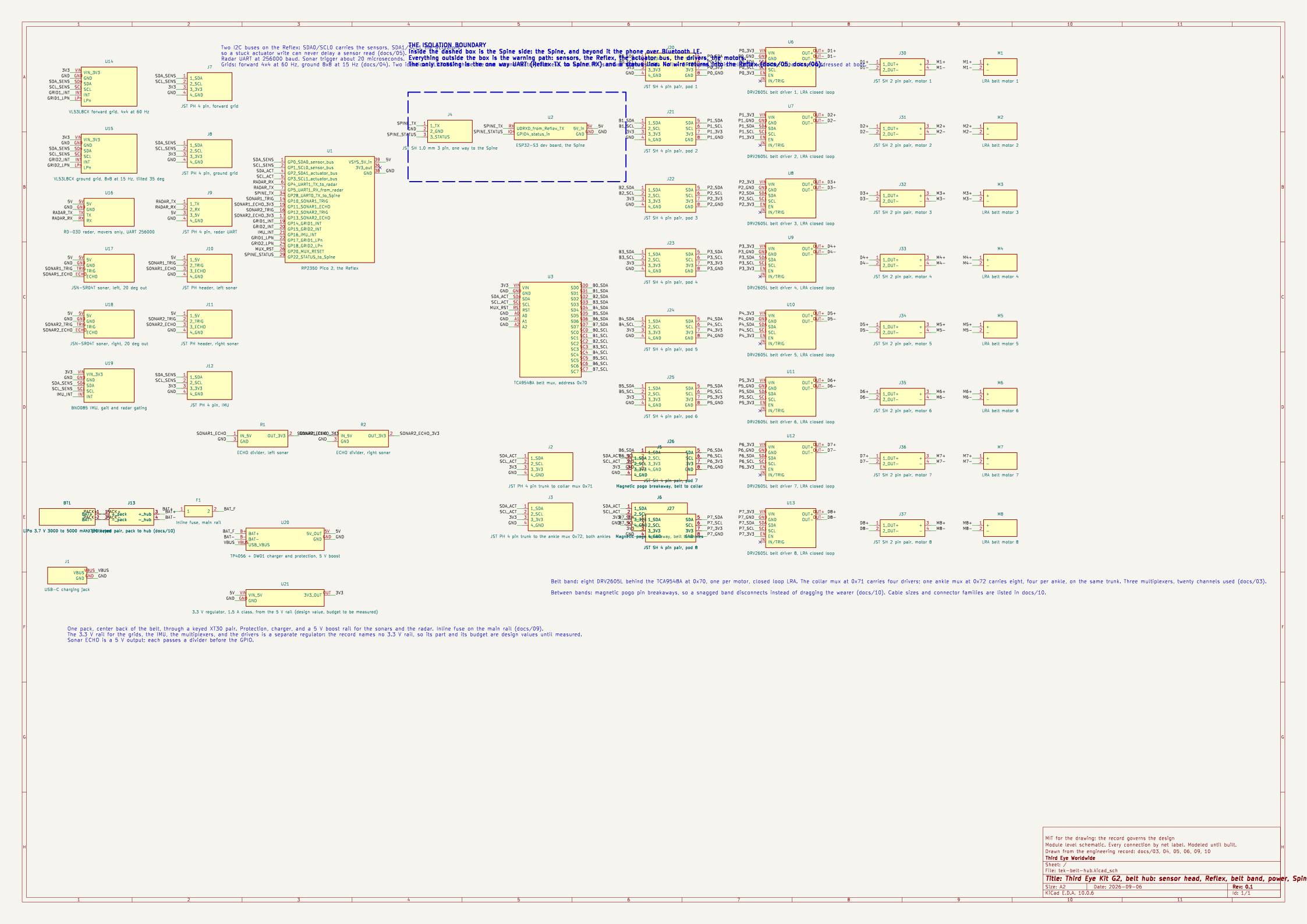
The belt hub schematic sheet: sensor modules on the left, the RP2350 Pico 2 in the center with its labeled pins, a dashed isolation boundary with the ESP32-S3 Spine to its right, the belt multiplexer and eight driver and motor pairs on the right, and the battery, fuse, charger and USB-C jack at the bottom left.
The belt hub schematic. Rendered by kicad-cli from the KiCad file in the repository: the two laser grids and the IMU on the Reflex's sensor I2C bus, the radar on its UART, the two sonars on trigger and echo lines; the belt multiplexer at 0x70 with its eight DRV2605L drivers and coin LRAs on the actuator bus; the trunk connectors and magnetic breakaways to the collar and ankle multiplexers; the pack, the fuse, the charger and the 5 V boost; and the one way link to the Spine across the isolation boundary. Every connection is a named net. kicad-cli's electrical rules check returns zero violations at its default severities. A module level schematic, modeled until built. Source: hardware/kicad/tek-belt-hub.kicad_sch, drawn from docs/03, 04, 05, 06, 09, 10.

Decision: one TI DRV2605L per motor in closed loop LRA mode, 20 drivers, grouped eight per TI TCA9548A I2C multiplexer, three multiplexers, on the actuator I2C bus of the Reflex controller.

Why the multiplexer: the DRV2605L address is fixed at 0x5A and cannot be changed, so twenty identical drivers cannot share a bus. TI's own DRV2605LEVM-MD reference board puts eight drivers behind a TCA9548A so they can be set up independently and played together. The multiplexer addresses are 0x70 to 0x77.

Alternatives rejected: per band microcontroller driving H bridges over a differential bus (fewer wires, but loses auto resonance and braking and makes field repair a reflash instead of a plug swap).

Timing: an RTP amplitude write over I2C at 400 kHz takes well under 1 ms; refreshing all 20 motors fits inside one control tick.

Repair: a motor pod or a driver is a plug replaceable module.

Source: docs/03-drivers-and-bus.md, the engineering record. Every number on this page is read from that file. If a fact is not in the record, it is measured on the bench, or it stays off this site.